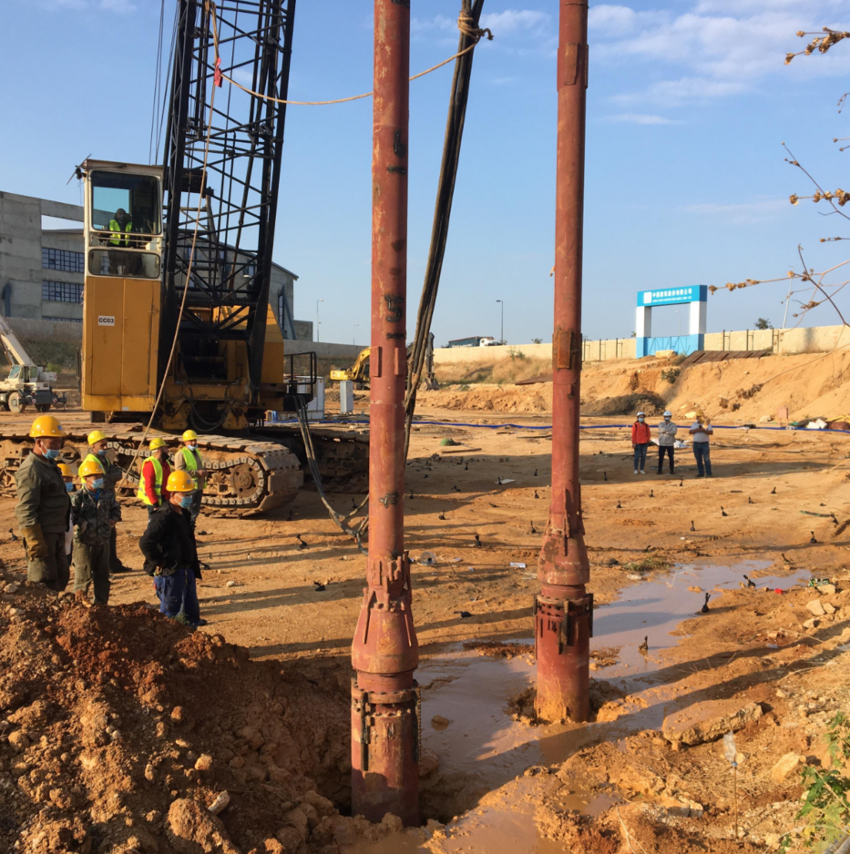
Ground improvement projects carry immense financial and operational stakes. On active construction sites, equipment downtime translates directly to severe project delays and compounding cost overruns. Integrating heavy vibratory equipment with complex electrical and hydraulic systems in unpredictable environments is highly prone to failure if not managed strictly. Site conditions change rapidly, and minor setup errors often cascade into catastrophic mechanical or electrical faults. Successful deployment requires moving far beyond basic vendor manuals. Project managers and site engineers must proactively identify mechanical, electrical, and operational failure points long before they halt production. Relying on assumptions during the initial setup phase guarantees poor compaction results and damaged machinery. Understanding the exact technical requirements of vibroflot installation and commissioning is necessary for maintaining site momentum and ensuring the structural integrity of the improved ground.
Key Takeaways
Mechanical Integrity is Non-Negotiable: Improper rigging and mismatched crane capacities are the leading causes of catastrophic physical failures during initial setup.
Electrical Vulnerabilities: Fluctuations in power supply and misconfigured control cabinets can cause immediate motor burnout or erratic compaction data.
The Human Element: Even premium equipment will fail without rigorous, site-specific operator training tailored to the exact soil conditions, retracting movements, and feed methods (top vs. bottom feed).
Vendor Accountability: True project security relies on a supplier's ability to provide rapid, on-site troubleshooting and robust installation support, not just hardware delivery.
The Realities of Vibroflot Installation and Commissioning
Defining Success Criteria
Establishing baseline metrics before equipment arrives on site prevents ambiguous performance evaluations later. A successful setup requires stable amperage readings that align with the manufacturer's specified no-load parameters. Operators must verify the correct vibration frequency while the probe is suspended in the air. Any deviation indicates internal mechanical binding or electrical supply issues. Secure mechanical linkages form the final baseline metric. Every flange, bolt, and hydraulic connection must withstand intense kinetic energy without loosening. If the equipment fails to meet these exact criteria during initial dry runs, ground penetration must not commence. We look for specific indicators during this phase. The motor should reach operating speed within seconds. The control panel must display balanced voltage across all three phases. The vibration isolator should absorb the majority of the kinetic energy, keeping the lifting head relatively still.
The "Plug-and-Play" Myth
Assuming vibratory ground improvement systems can be deployed instantly is a dangerous misconception. Heavy-duty compaction equipment demands a strict, phased implementation approach. The process begins with a comprehensive pre-assembly inspection. Crews check for transit damage and verify all component serial numbers against the shipping manifest. Next, we execute dry testing. This involves suspending the assembled unit and running the motor briefly to check rotation direction and baseline vibration. Finally, wet testing occurs. The probe is driven into a designated test location to monitor performance under actual soil resistance and water pressure. Skipping any phase guarantees operational failure.
We enforce a strict sequence for the testing phases to isolate potential faults early:
Uncrate all components and inspect the main vibrator body for dents or deep abrasions.
Verify the integrity of the O-rings and seals on all extension tube flanges.
Connect the control cabinet to the generator and test the main breaker without the motor attached.
Assemble the vibration isolator, extension tubes, and vibrator using calibrated torque wrenches.
Suspend the entire assembly one meter off the ground.
Engage the motor for exactly ten seconds to verify phase rotation and listen for abnormal bearing noise.
Lower the probe into a pre-drilled starter hole and initiate water jetting.
Penetrate to the target depth while monitoring the amperage spike and water return at the surface.
Site-Specific Variables and Technique Alignment
Environmental factors dictate the commissioning timeline and heavily influence equipment performance. Temperature extremes alter the viscosity of hydraulic fluids and affect the cooling capacity of electrical control cabinets. Site accessibility determines the size of the crane that can be deployed, directly impacting the maximum depth of treatment. Water supply pressure is another variable. Side-water compaction requires high-volume, high-pressure delivery to break surface tension and allow penetration. Furthermore, the chosen ground improvement technique dictates the setup. Pure compaction relies on different amplitude settings and penetration speeds compared to stone column formation, requiring specific adjustments during the initial vibroflot commissioning phase. You must adapt the equipment to the site, not the other way around. If the site features dense clay layers above the target granular soil, the water jetting system requires higher pressure nozzles. If the site is in a remote location, the spare parts inventory must be doubled.
Mechanical Failures: The Vibroflot Crane Connection and Suspension
Weight Capacity and Rigging Miscalculations
Underestimating the total dynamic weight of the assembly is a primary cause of rigging failure. The calculation must include the vibroflot probe, all extension tubes, the vibration isolator, water hoses, electrical cables, and the material drag created during extraction. When extracting the probe from dense or cohesive soils, suction forces multiply the effective weight significantly. Crane capacity must be strictly rated to carry this entire suspended configuration under dynamic load conditions, especially during deep penetration and extraction phases.
Improper vibroflot crane connection leads to rapid, excessive wear on the crane wire rope. If the lifting head is not perfectly aligned, the eccentric forces transfer directly to the rigging hardware. This misalignment causes metal fatigue in shackles and lifting pins. In worst-case scenarios, compromised rigging results in the catastrophic dropping of the probe, destroying the equipment and endangering site personnel. We always mandate a safety factor of at least 2.5 when selecting shackles and wire ropes for vibratory applications.
Dynamic Load Calculation Components
Component
Weight Contribution
Dynamic Multiplier Factor
Main Vibrator Probe
Base weight (e.g., 2000 kg - 4000 kg)
1.5x during initial startup
Extension Tubes
Cumulative weight based on depth
1.2x during extraction
Vibration Isolator
Fixed weight (e.g., 500 kg - 1000 kg)
1.0x (Static)
Hoses and Cables
Variable based on length and water volume
1.1x due to fluid movement
Soil Suction Force
Variable based on soil cohesion
Up to 3.0x in heavy clays
Vibration Isolator and Extension Tube Misalignment
Extension tubes deliver the necessary depth reach, but their connection points are highly vulnerable. Failing to properly torque connection bolts between these tubes allows microscopic movements during operation. This movement rapidly shears the bolts, leading to structural separation underground. Crews must use calibrated torque wrenches and apply thread-locking compounds as specified by the manufacturer. We recommend marking each torqued bolt with a paint pen to visually verify it has not backed out after the first few hours of operation.
The vibration isolator serves as the barrier between the active probe and the crane. It absorbs the upward kinetic energy generated by the eccentric weight. A malfunctioning or improperly installed isolator transfers destructive vibrations directly back into the crane boom. This continuous shaking causes structural damage to the crane, disrupts the operator's control, and frequently triggers the crane's load moment indicator (LMI) safety systems. Inspect the heavy-duty rubber dampeners inside the isolator before every shift. If they show signs of cracking or excessive compression, replace them immediately.
Water and Air Line Integrity
High-pressure water jetting hoses and compressed air lines sustain severe abuse during the initial lifting and lowering phases. Common failure points occur at the connection manifolds and along the exterior of the extension tubes where hoses rub against abrasive soils. A burst water line instantly halts penetration and can cause the surrounding soil to collapse around the probe.
Mitigation requires strict hose routing strategies. Lines must be secured tightly against the extension tubes using heavy-duty straps or custom brackets. Operators must ensure enough slack exists at the pivot points to prevent pinching or severing when the assembly swings. Regular visual inspections of hose jackets for abrasion are mandatory before every shift. We use reinforced, wire-braided hoses for the bottom ten meters of the assembly, as this section experiences the most severe friction against the borehole walls.
Electrical Risks During Vibroflot Commissioning
Faults in the Vibroflot Electrical Control System
The control cabinet acts as the brain of the operation, managing massive electrical loads. Common wiring errors frequently occur between the generator, the control cabinet, and the motor. Loose terminal connections caused by transit vibrations lead to arcing, localized overheating, and blown fuses. Every connection within the vibroflot electrical control system must be retightened and verified by a qualified electrician prior to power-up.
Phase reversal is a severe risk during initial wiring. If the three-phase power lines are connected out of sequence, the internal eccentric weight rotates in the wrong direction. While the motor will still run, backward rotation severely impacts compaction efficiency. More dangerously, it can cause threaded internal mechanical components to unscrew during operation, leading to total internal destruction of the vibrator. Always use a phase rotation meter on the output terminals of the control cabinet before connecting the main motor cable.
Power Supply Inconsistencies and Generator Sizing
Using undersized generators is a frequent and costly mistake. The massive starting current, known as inrush current, required to spin up the heavy eccentric weight can be three to five times higher than the continuous running current. If the generator cannot handle this initial spike, voltage drops instantly. This causes the control cabinet contactors to chatter and the motor to stall.
Large construction sites often require long cable runs between the generator and the control cabin. Extended cable lengths create natural electrical resistance, leading to significant voltage drops at the motor terminals. Operating the motor at lower-than-rated voltages causes it to draw excessive current to maintain torque. This generates extreme heat, degrades the stator insulation, and ultimately results in premature motor failure.
Generator Sizing and Cable Length Guidelines
Motor Power Rating (kW)
Minimum Generator Size (kVA)
Max Cable Length (Standard Gauge)
Recommended Cable Upgrade Length
75 kW
150 kVA
50 meters
> 50 meters
130 kW
250 kVA
40 meters
> 40 meters
180 kW
350 kVA
30 meters
> 30 meters
Sensor and Data Logging Calibration
Modern ground improvement relies heavily on real-time data logging to verify compaction standards. Calibrating depth encoders, amperage transducers, and pressure sensors during commissioning is an absolute necessity. Depth sensors mounted on the crane winch must be zeroed accurately at ground level to ensure treatment depths meet engineering specifications.
Recording false compaction data due to uncalibrated or damaged sensors jeopardizes the entire project. If the amperage sensor reads artificially high, the operator will stop compaction prematurely, leaving loose soil zones. If it reads artificially low, the operator will over-compact, wasting time and risking equipment jamming. All sensor outputs must be cross-referenced with manual measurements during the wet testing phase. We manually measure the first three compaction points with a weighted tape measure to verify the digital depth encoder is tracking accurately.
Operational Bottlenecks and Human Error
The Cost of Inadequate Vibroflotation Operator Training
A massive gap exists between theoretical knowledge and practical, on-site operation. Heavy equipment behaves differently depending on soil stratigraphy. Without rigorous vibroflotation operator training, crews struggle to manage the precise timing of penetration, holding, and extraction phases. Operating the equipment is not simply about lowering a weight into the ground; it requires reading the amperage gauge to understand soil density changes in real-time.
Incorrect retracting movements directly compromise the ground improvement design. The vibroflot must be started and stopped at predetermined times and specific depth intervals. Failing to adhere to these intervals leads to inconsistent compaction and leaves unstable soil masses hidden beneath the surface. Furthermore, untrained operators frequently cause equipment jamming. Forcing penetration into dense soil layers without adequate water jetting creates a vacuum effect, locking the probe underground and requiring costly excavation to retrieve it.
Misinterpreting Soil Conditions During Initial Testing
Applying rigid installation parameters to variable soil profiles guarantees poor results. Soil is rarely uniform. Operators must adjust their techniques as they encounter different layers. Cohesive soils react very differently than granular fills. In cohesive soils, the hole typically does not fall in on itself. This allows the probe to be removed while aggregate is incrementally dumped into the void to form a vibro stone column.
Conversely, granular fills require different stabilization tactics, often relying on pure compaction where the surrounding soil collapses against the probe. The feed method also drastically alters commissioning protocols. Top feed systems are free-hanging and rely on surface aggregate dumping. Bottom feed systems are vastly more complex, requiring the calibration of material hoppers, compressed air pressure lines, and tremie pipe flow rates to ensure stone is delivered directly to the tip of the probe without clogging.
Common Commissioning Faults and Mitigation Strategies
Fault Category
Observed Symptom
Probable Root Cause
Mitigation Action
Mechanical
Crane boom shaking violently
Vibration isolator failure or bypassed dampeners
Inspect isolator rubber elements; verify lifting head alignment.
Electrical
Motor stalls immediately on startup
Generator undersized for inrush current
Upgrade generator kVA rating; check for voltage drop across cables.
Operational
Probe refuses to penetrate topsoil
Insufficient water jetting pressure
Clear blocked nozzles; verify water pump output matches specifications.
Data Logging
Erratic depth readings on monitor
Winch encoder slipping or uncalibrated
Re-zero encoder at ground level; tighten mounting brackets.
Evaluating Your Vibroflot Equipment Supplier for Implementation Success
Assessing the Depth of Vibroflot Installation Support
Procuring the equipment is only the first step. The true value of a vendor lies in their commissioning Service Level Agreement (SLA). Project managers must determine if the supplier sends a qualified technician to the site or relies entirely on remote phone support. Remote support is insufficient for diagnosing complex hydraulic or electrical faults on an active site. Comprehensive vibroflot installation support requires hands-on expertise.
A reliable supplier will conduct a pre-mobilization site audit. This audit verifies that the contractor's crane capacities align with the equipment's dynamic weight. It also involves reviewing the geotechnical soil reports to confirm that the selected probe size, motor power, and feed method are actually capable of achieving the required compaction densities in that specific geology. We expect suppliers to provide a detailed mobilization checklist weeks before the equipment ships.
Warranty, Spare Parts, and On-Site Troubleshooting
Decision-makers often face a trade-off between lower upfront equipment costs and long-term operational security. Purchasing cheaper equipment from a vendor with no localized spare parts inventory is a massive risk. When a proprietary component fails, waiting weeks for international shipping paralyzes the project. A premium vibroflot equipment supplier maintains regional parts hubs and offers immediate dispatch.
To mitigate downtime, specific critical spare parts must be mandated in the initial procurement contract. Sites should never operate without backup electrical contactors, high-amperage fuses, replacement hydraulic hoses, and specialized high-tensile connection bolts. Having these parts physically on site during commissioning allows technicians to resolve initial teething problems in minutes rather than days.
We require the following spare parts to be on-site before commissioning begins:
Complete set of replacement O-rings and flange seals.
Three sets of high-amperage fuses for the main control cabinet.
One spare main contactor matched to the motor's kW rating.
Fifty meters of reinforced water jetting hose with matching quick-connect fittings.
Two complete sets of high-tensile bolts for the extension tube connections.
Conclusion
To ensure a smooth and successful deployment of your ground improvement equipment, execute the following next steps immediately:
Initiate a pre-installation mechanical and electrical audit checklist with your chosen vendor at least 30 days prior to equipment mobilization.
Verify all crane load charts against the maximum dynamic weight of the fully assembled vibroflot, extension tubes, and anticipated soil suction forces.
Mandate a localized spare parts inventory on site, specifically targeting high-wear items like hoses, fuses, and connection bolts before the first dry test.
Schedule dedicated, site-specific training days for operators to practice retracting movements and gauge reading under direct vendor supervision.
FAQ
Q: What is the most common cause of motor failure during vibroflot commissioning?
A: The most frequent cause is using undersized generators that fail to support the massive starting current required by the motor. This inability to handle inrush current leads to severe voltage drops across the cables, causing the motor to overheat rapidly and eventually burn out the stator insulation.
Q: How do you verify a secure vibroflot crane connection?
A: Verification requires a strict inspection of the vibration isolator and all lifting hardware. Crews must check shackle ratings against the total dynamic weight. Finally, dynamic load testing must be performed by suspending the fully assembled configuration and running the motor in the air prior to any ground penetration.
Q: Why is phase rotation critical in the vibroflot electrical control system?
A: Incorrect phase rotation causes the internal eccentric weight to spin backward. This drastically reduces the compaction force delivered to the soil and creates a severe risk of unscrewing internal threaded mechanical components, which can destroy the vibrator from the inside out.
Q: What should be included in standard vibroflotation operator training?
A: Standard training must cover strict safety protocols, precise crane signaling, and real-time amperage monitoring. Operators must also learn water pressure control, the exact timing for retracting movements at specific depth intervals, and emergency shutdown procedures to prevent equipment jamming.
Q: How long does standard vibroflot installation and commissioning take?
A: A standard commissioning phase typically takes two to five days. This timeline depends heavily on site readiness, the complexity of the equipment configuration, environmental variables, and whether an experienced vendor technician is physically present to guide the dry and wet testing phases.
Q: What is the difference in commissioning a top feed vs. bottom feed vibroflot?
A: Top feed systems are simpler, relying on free-hanging probes and managing incremental aggregate dumping from the surface. Bottom feed systems add significant complexity, requiring the meticulous calibration of the material hopper, compressed air pressure lines, and tremie pipe flow rates to prevent stone blockages.