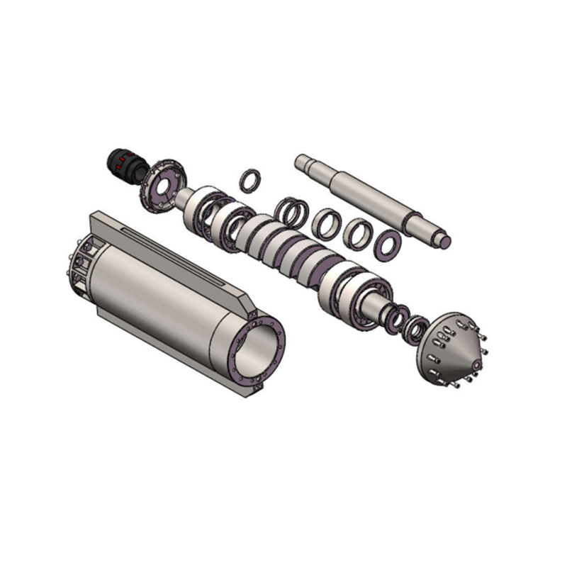
Deep soil compaction projects demand relentless mechanical performance from every piece of machinery on site. Unplanned downtime brings severe financial consequences that compound daily. Equipment failure directly threatens project timelines, ruins profit margins, and jeopardizes the required load-bearing capacities of the foundation. Continuous vibroflotation operation places extreme mechanical, thermal, and abrasive stresses on the entire probe assembly. Standard maintenance schedules often fail under these high-load conditions, especially when working in dense soil matrices. You need a more aggressive, field-tested approach.
Shifting to proactive, predictive maintenance strategies extends equipment lifecycles significantly. It reduces catastrophic down-hole failures and ensures consistent ground improvement results across the site. Mastering vibroflotation equipment maintenance remains essential for operational survival. By understanding the specific wear patterns of your machinery, you can intervene before minor degradation becomes a major breakdown.
Key Takeaways
Predictive Over Reactive: Shifting from reactive repairs to continuous vibroflot operation maintenance prevents project-halting breakdowns.
Critical Wear Zones: The motor cooling system, vibration body, elastomeric dampers, and feed systems (like gravel hoppers) are the highest-risk failure points requiring specialized inspection protocols.
Supplier Partnership: Long-term operational success depends heavily on selecting a vibroflotation equipment supplier that provides rapid parts availability and specialized technical service.
Data-Driven Interventions: Utilizing telemetry and operational data allows for precise scheduling of component replacements before catastrophic failure occurs.
The Mechanics of Wear in Continuous Vibroflot Operation
Problem Framing & Success Criteria
Normal wear happens gradually over hundreds of operating hours. Accelerated wear destroys components in days. You must distinguish between the two on the job site. Deep foundation compaction relies on heavy eccentric weights spinning at high speeds, typically between 1,500 and 3,000 RPM. This rotation generates immense centrifugal force, often exceeding 30 to 50 tons. This force transfers through the heavy-duty bearings into the outer steel casing, and finally into the surrounding soil matrix. The primary success criteria for any maintenance program include maximizing Mean Time Between Failures (MTBF) and ensuring the equipment consistently achieves target soil density. If a probe loses amplitude due to bearing wear or internal friction, the soil compaction fails, and the foundation will not meet engineering specifications.
Power Systems: Electric vs. Hydraulic Probes
Different power delivery methods create unique wear profiles. You must tailor your inspection routines to the specific drive system of your fleet.
Electric units rely on high-voltage motors housed directly inside the vibrating casing. They remain highly vulnerable to stator insulation breakdown. Long cable runs from surface generators cause voltage drops. When voltage drops, the motor draws higher amperage to maintain wattage, generating excess heat that attacks the copper windings. Hydraulic systems pump high-pressure fluid down to a hydraulic motor. They suffer from fluid contamination and pressure loss. High-frequency vibration causes micro-abrasions on hydraulic hoses as they rub against the inside of the follower tubes. The outer rubber sheath degrades, leading to sudden, catastrophic hose ruptures that dump hydraulic fluid into the ground.
Thermal Stress and Motor Degradation
Continuous high-frequency vibration generates extreme internal heat. The eccentric weights spin rapidly, creating massive friction within the spherical roller bearings. These bearings carry the entire centrifugal load. If thermal limits are exceeded, the lubricating grease breaks down. The oil separates from the thickener, losing its viscosity and turning to liquid. Once the grease fails, metal grinds against metal. Bearing failure follows within minutes, often welding the rollers to the races. For electric units, excessive heat melts the Class H resin coating on the stator windings. This causes a dead short, requiring a complete and expensive motor rewind.
Abrasive Wear on the Outer Casing and Feed Systems
Subterranean environments act like a giant belt sander against the equipment. Highly abrasive soil matrices, such as dense silica sands and crushed gravels, constantly grind against the steel casing. This affects both top-feed and bottom-feed operations differently.
Top-Feed Water Jetting: Pumping water through the nose cone helps the probe penetrate dense soil. The water flushes the spoil up the annulus between the probe and the soil. This upward flow of sandy water heavily erodes the outer casing. Using untreated site water introduces risks of internal corrosion and mineral scaling. The high-pressure jetting nozzles slowly erode and widen, dropping the water pressure required to break up hardpan layers.
Bottom-Feed Systems: Stone drops down a tremie pipe attached to the side of the probe. The continuous flow of crushed aggregate severely erodes the inside of the tremie pipe and the gravel hopper. High-pressure air flushing used in these systems risks abrasive dust blowback. Fine silica dust penetrates the lower seal assemblies, destroying the mechanical seals and allowing groundwater to flood the motor chamber.
Fatigue in Dampers, Couplings, and Mounts
Isolation dampers separate the violent vibrating mass from the follower tubes and the crane line. They endure severe mechanical fatigue. The elastomeric material stretches and compresses thousands of times per minute. This rapid movement causes rubber hysteresis, where kinetic energy converts into internal heat. Over time, the core of the rubber bakes, hardens, and cracks. Drill-rig mounting brackets face different vibrational stresses compared to traditional crane-suspended setups. Rigid mast mounts absorb lateral shocks directly, causing rapid weld fatigue on the carriage plates and mast tracks.
Core Protocols for Vibroflotation Equipment Maintenance
Vibroflot Motor Cooling Maintenance
Cooling systems require vigilant, daily monitoring. Closed-loop water cooling systems pump fluid through a jacket surrounding the motor stator. Site water often contains silt, mud, and dissolved minerals. These contaminants build up inside the narrow passages of the cooling jacket. This scale acts as a thermal insulator, trapping heat inside the motor and preventing it from transferring to the cooling water.
You must flush cooling jackets regularly using industrial descaling solutions. Check the flow rates at the surface return line using a flow meter. A drop in flow indicates a blockage forming down-hole. Verify the accuracy of internal thermal sensors during every maintenance window. If a sensor drifts or fails, the control panel will not trip the power before stator burnout occurs. Proper vibroflot motor cooling maintenance prevents catastrophic electrical failures and keeps the equipment running through long shifts.
Vibroflot Vibration Body Wear Inspection
The outer casing protects the internal mechanics from crushing subterranean hydrostatic pressure. As the casing wears thin from sand abrasion, structural integrity drops. If the wall becomes too thin, the pressure will crush the casing, instantly flooding the motor. You must establish a strict framework for measuring casing wall thickness.
Clean the outer casing thoroughly with a wire brush to remove caked mud and rust.
Use an ultrasonic thickness gauge to measure the steel wall. Take readings every 90 degrees around the circumference, at 1-meter intervals along the length of the probe.
Map the wear patterns on a grid. The lower third of the probe, just above the nose cone, typically degrades the fastest.
Establish hardfacing and hard-welding schedules. Apply crosshatch or dot-pattern tungsten carbide welds to restore the protective layer before the base metal wears away.
Inspect the nose cone and jetting nozzles for blockages and erosion. Replace eroded nozzles immediately to maintain optimal jetting pressure.
Bottom-feed systems require additional checks. Inspect gravel hoppers, tremie pipes, and material delivery chutes. Continuous stone backfill causes severe internal abrasion. Check the hopper door hinges and pneumatic seals for aggregate damage. Consistent vibroflot vibration body wear inspection keeps the probe watertight and structurally sound.
Vibroflot Vibration Damper Replacement Schedules
Elastomeric and mechanical dampers have a finite lifecycle under continuous load. You must replace them before they fail completely and drop the probe down the hole. Visual indicators of degradation include surface cracks, bulging rubber, and separated bonding plates where the rubber meets the steel flange. Operational indicators include increased vibration transmission to the crane line, causing the crane boom to shake violently.
Follow strict technical requirements for field replacement. Secure the crane line and properly block the follower tube on the ground. Disconnect the flange bolts evenly to prevent binding. Inspect the mating surfaces for burrs or rust that could prevent a flush fit. Install the new damper and torque the bolts to factory specifications in a star pattern to ensure even compression. Timely vibroflot vibration damper replacement protects your lifting equipment from structural fatigue and prevents dropped loads.
Evaluating Maintenance Strategies: Cost vs. Reliability
Run-to-Failure vs. Predictive Maintenance Models
Delayed maintenance offers an illusion of short-term savings. The exponential costs of catastrophic down-hole failures quickly erase those savings. If a probe floods underground, you lose the motor, the bearings, the internal sensors, and days of production while you fish the dead unit out of the ground. Condition-based monitoring proves vastly superior to strict time-based intervals. You replace parts when their physical condition dictates, not just because a calendar says so. Effective continuous vibroflot operation maintenance relies entirely on this predictive approach.
Maintenance Strategy
Operational Approach
Risk of Catastrophic Failure
Impact on Project Timeline
Run-to-Failure
Operate equipment until it breaks down completely.
Extremely High
Severe delays due to unexpected downtime and complex field recoveries.
Time-Based Preventative
Replace parts at strict hourly intervals regardless of condition.
Moderate
Predictable, but wastes usable part life and increases parts consumption.
Predictive (Condition-Based)
Monitor telemetry and wear data to schedule repairs precisely.
Low
Minimal disruption; repairs align with scheduled shift changes.
Telemetry and Real-Time Data Monitoring
Modern control panels and data loggers serve as your first line of defense against equipment failure. They track amperage draw, hydraulic pressure, frequency shifts, and temperature spikes in real-time. These metrics act as leading indicators of component wear. A slow, steady increase in baseline amperage over a week suggests bearing friction is rising. Sudden temperature spikes indicate a cooling system blockage. Monitoring penetration depth and compaction data highlights mechanical inefficiencies. If the probe takes twice as long to reach the target depth in known soil conditions, the amplitude has likely dropped, indicating internal mechanical issues.
OEM Parts vs. Aftermarket Alternatives
Procurement teams often debate utilizing original equipment manufacturer parts versus cheaper aftermarket alternatives to save money. High-frequency applications demand exact engineering tolerances. Aftermarket bearings might feature standard internal clearances. Vibroflot bearings require special C4 or C5 internal clearances to accommodate massive thermal expansion during operation. Standard bearings seize up within hours under these conditions. Using mismatched parts risks voided warranties, destroys internal mechanics, and guarantees premature failure.
Selecting a Vibroflotation Equipment Supplier for Long-Term Reliability
Criteria for Evaluating Supplier Technical Capabilities
Procurement and fleet managers must look beyond the initial capital expenditure of the machinery. You need a reliable partner, not just a vendor. Evaluate their engineering support and inventory depth before signing a contract. Do they understand the nuances of both electric and hydraulic systems? A reliable vibroflotation equipment supplier stocks critical wear parts locally or regionally. They provide immediate troubleshooting assistance when a rig goes down in the field, minimizing your downtime.
The Role of a Dedicated Vibroflot Maintenance Technical Service
Complex overhauls require factory-trained technicians. Tasks like eccentric weight bearing replacement, motor rewinding, and hydraulic pump calibration demand clean-room environments and specialized tooling. Field mechanics cannot perform these tasks in the dirt without contaminating the internal components. Access to a dedicated vibroflot maintenance technical service ensures rebuilds meet exact factory specifications. Look for suppliers that provide on-site training for your internal mechanics. Educated operators and mechanics break equipment less often and catch warning signs earlier.
Parts Availability and Supply Chain Resilience
A supplier's global or regional footprint directly impacts lead times for replacement parts. Custom hardfaced casings, specialized elastomeric dampers, and high-voltage stators are not off-the-shelf items you can buy locally. If your supplier lacks supply chain resilience, your project stalls waiting for a cargo ship to arrive. Audit their warehouse capabilities before committing to their ecosystem. Ensure they maintain a robust stock of the specific wear parts your fleet requires for the duration of your project.
Implementation Risks and Mitigation Tactics
Operator Error and Training Deficits
Improper operation accelerates wear faster than any harsh soil condition. Operators often force the probe into dense layers without adequate water jetting, putting massive structural strain on the casing. They ignore amperage spikes on the control panel, burning out the motor. They execute incorrect raising increments, which traps the probe in collapsing soil. Yanking a stuck probe with the crane destroys the vibration dampers and damages the crane boom.
Mitigation: Mandate strict operational parameters. Set hard limits on maximum amperage and pull-up force. Implement continuous operator training via the control panel data. Teach operators to read the soil feedback through the machine's telemetry rather than forcing the equipment.
Environmental Variables
Site conditions dictate equipment lifespan. Utilizing highly saline groundwater or sediment-heavy pond water for jetting and cooling accelerates internal corrosion rapidly. The minerals bake onto the hot motor casing, creating a thick layer of scale. Sand particles destroy water pump impellers and erode the jetting nozzles.
Mitigation: Implement strict water filtration protocols on site. Use settling tanks to remove heavy sediments before pumping water to the probe. Mandate daily post-operation flushing routines using clean, fresh water to clear the cooling jackets and prevent scale buildup.
Field Repair Limitations
Performing complex maintenance in contaminated, dusty field environments introduces massive risk. Opening a bearing housing in a sandstorm guarantees premature failure. Dirt enters the grease, acting as a grinding paste against the polished steel rollers.
Mitigation: Establish clear guidelines delineating field repairs from workshop repairs. Routine greasing, visual inspections, and damper swaps can happen on-site. Bearing replacements, motor repairs, and seal overhauls must occur in a clean-room workshop environment. Keep spare probe assemblies on hand to swap out entirely, allowing the damaged unit to be repaired properly off-site.
Conclusion
Reducing wear in continuous vibroflotation operation is not about eliminating wear entirely. It is about managing it predictably through rigorous, data-backed maintenance. You must ensure target soil density is achieved without interruption. Choosing the right maintenance partners requires verifying their technical expertise, ensuring a robust OEM parts supply, and confirming responsive field service capabilities.
Take the following steps to protect your equipment fleet:
Audit your current fleet's maintenance logs to identify recurring failure patterns and component lifespans.
Implement weekly ultrasonic casing inspections to track abrasive wear rates accurately across all active probes.
Install modern data loggers on older rigs to capture real-time amperage, hydraulic pressure, and temperature metrics.
Consult with a certified technical service provider to optimize your preventative replacement schedules based on site-specific soil conditions.
FAQ
Q: What is the standard interval for vibroflot vibration damper replacement?
A: Replacement intervals depend heavily on operating hours and continuous operation stress. Typically, dampers require replacement every 1,000 to 2,000 hours. You must prioritize condition-based replacement. Inspect them daily for micro-tears, bulging, or increased vibration transmission to the crane line. Dense soil compaction accelerates fatigue, requiring earlier replacement.
Q: How do you perform a vibroflot vibration body wear inspection?
A: Use an ultrasonic thickness gauge to measure the steel casing wall. Map the measurements on a grid to track degradation over time. Visually inspect the hardfacing welds for excessive wear. Check the structural integrity of the nose cone, water jetting nozzles, and bottom-feed tremie pipes for abrasive erosion.
Q: What are the signs that motor cooling maintenance is required?
A: The primary signs include abnormal temperature readings on the control panel and sudden thermal tripping. You will also notice increased amperage draw as the motor struggles with heat. Reduced water flow rates at the return line indicate severe mineral scaling or mud blockages inside the cooling jacket.
Q: Why does continuous operation require different maintenance than standard equipment?
A: Vibroflots endure a unique combination of high-frequency vibration, deep subterranean pressure, and highly abrasive soil environments. This requires specialized mechanical tolerances, such as C4 or C5 bearing clearances. Standard equipment maintenance schedules cannot account for the rapid thermal and abrasive degradation experienced down-hole during continuous compaction.
Q: Are there specific maintenance tasks for bottom-feed systems?
A: Yes. You must inspect the gravel hoppers and hopper doors for severe abrasive wear from the stone backfill. Check the internal material delivery chutes and tremie pipes for blockages or thinning walls. Assess the structural integrity and weld health of the drill-rig mounting brackets daily.
Q: What should I look for in an equipment supplier?
A: Prioritize a robust supply chain that guarantees rapid delivery of critical wear parts. Ensure they offer access to specialized technical service for complex rebuilds. Look for a supplier with a proven track record of equipment durability in soil conditions similar to your specific project requirements.
Q: Can maintenance be performed entirely on-site?
A: No. While routine greasing, visual inspections, and minor part swaps like dampers can be done on-site, major overhauls cannot. Bearing replacements, motor rewinds, or hydraulic rebuilds require a clean, controlled workshop environment. Opening internal chambers in dusty field conditions leads to immediate contamination and premature failure.