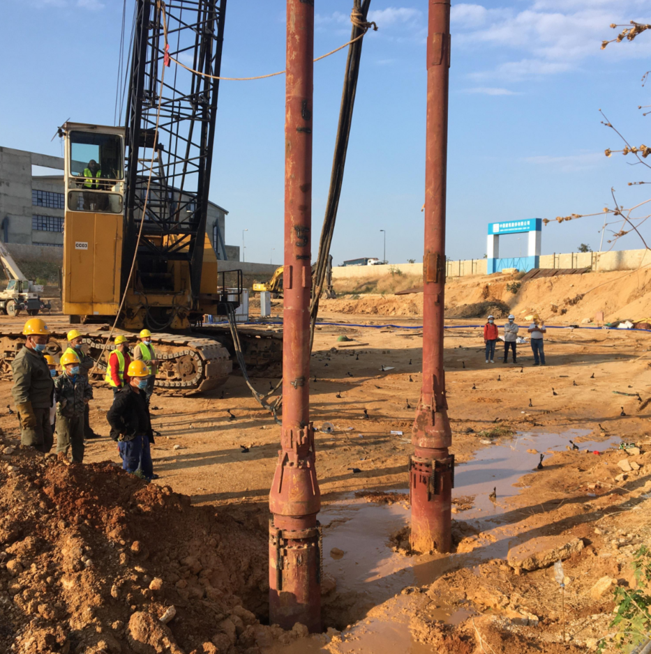
Deep foundation projects leave no room for error. When you stabilize ground for major infrastructure, equipment failure or inadequate compaction leads directly to structural settlement. You must match specific geotechnical requirements with the correct mechanical specifications. Soil type, shear strength, and treatment depth dictate your heavy compaction machinery needs. Guesswork has no place on a job site. You need hard data to select the right tools. We built this guide to give you an evidence-based framework for evaluating technical specifications. You will learn how to assess compliance standards and vendor reliability before you request a formal quotation. By aligning site data with mechanical capabilities, you ensure continuous operation. You will hit your target soil densities and keep your project on schedule.
Methodology Matching: The choice between top feed and bottom feed vibroflot options must be dictated strictly by site soil composition and groundwater levels.
Power & Amplitude: Selecting electric vibroflotation equipment for deep foundation work requires balancing motor kW output with eccentric moment to achieve target soil densities and required lift thicknesses.
Risk Mitigation: Procuring CE certified vibroflotation equipment is non-negotiable for ensuring operational safety, regulatory compliance, and insurance validity.
Defining Project Success Criteria for Ground Improvement
Every successful ground improvement project begins with the Geotechnical Baseline Report (GBR). The GBR dictates your exact equipment requirements. There is no universal, one-size-fits-all vibroflot. You must analyze the soil stratigraphy, groundwater elevation, and bearing capacity targets. Purchasing machinery without aligning it to the GBR guarantees poor compaction results. You must secure the right vibroflotation equipment for ground improvement to meet strict engineering tolerances.
Soil Types and Granularity
Granular soils require different treatment mechanics than cohesive soils. Clean sands and gravels respond excellently to vibro compaction. The intense lateral vibrations temporarily liquefy the soil. This allows the granular particles to rearrange into a much denser state. You measure success by achieving specific relative density percentages or target Standard Penetration Test (SPT) N-values. Cone Penetration Testing (CPT) tip resistance provides another metric to verify the densification of sand layers.
Cohesive soils, silts, or mixed stratigraphies do not densify through vibration alone. They require vibro replacement. You must construct dense stone columns to reinforce the weak ground. The equipment must displace the native soil and compact the imported aggregate. The success criteria here involve the diameter, continuity, and stiffness of the installed stone columns. You verify this through plate load tests and continuous monitoring of the motor amperage during installation.
Depth and Lift Thickness Requirements
Target treatment depths directly influence your equipment configuration. Deep compaction requires heavy-duty extension tubes. These tubes deliver power and jetting fluids to the probe tip. Greater depths demand robust flange connections to withstand intense torsional forces. You must also evaluate the lifting capacity of your supporting crawler crane. The crane must safely handle the combined weight of the vibroflot, extension tubes, and material hoses.
Lift thickness parameters dictate how you withdraw the probe. You compact the soil in vertical stages, or lifts. Typical lift thicknesses range from 0.5 to 1.0 meters. The equipment must sustain maximum amplitude during each lift. Uniform compaction at greater depths requires consistent energy transfer. If the machine lacks sufficient eccentric force, the lower lifts will fail quality control tests.
Production Targets and Site Preparation
Project schedules rely on strict production targets. You must calculate the required compaction yields in cubic meters per hour. Equipment selection directly impacts this yield. A high-penetration probe reduces the time spent reaching the target depth. Efficient material feeding systems speed up the withdrawal and compaction phases. You must match the machinery's theoretical output with your actual site logistics to maintain the critical path schedule.
Review the GBR to identify the depth of the bearing stratum.
Calculate the total linear meters of compaction required across the site grid.
Determine the required crane boom length based on the maximum treatment depth plus clearance.
Size the generator capacity to handle the peak starting current of the vibroflot motor.
Establish a clear traffic management plan for wheel loaders delivering aggregate.
Solution Categories: Top Feed and Bottom Feed Vibroflot Options
Selecting the correct feed method is the most critical technical decision. You must evaluate the site conditions to choose between top feed and bottom feed vibroflot options. Using the wrong method causes project failure, severe delays, and massive material waste.
Top Feed (Vibro Compaction)
Top feed systems utilize high-pressure water jets located at the tip of the probe. The water flushes out fine particles and reduces friction. This allows the heavy probe to penetrate deep into the ground under its own weight. Once at the target depth, the water flow is reduced. The operator slowly withdraws the probe while vibrating. Additional sand or gravel is added from the surface to fill the void.
This method excels in clean, granular soils with low fines content. It is highly efficient for large-scale land reclamation projects. However, implementation carries specific logistical risks. You need a massive, continuous water supply. Site drainage becomes a major operational challenge. You must manage environmental runoff and control sediment effectively. Slurry containment ponds are often necessary to filter the return water before discharge.
Bottom Feed (Vibro Replacement / Stone Columns)
Bottom feed systems operate dry, utilizing compressed air instead of water. The equipment features a tremie pipe attached alongside the main vibroflot casing. A specialized hopper loads crushed stone into the system. The aggregate travels down the tremie pipe and exits directly at the probe tip. The machine compacts the stone outward into the surrounding soil, building a dense column from the bottom up.
This method is mandatory for weak, cohesive, or mixed soils. It provides high bearing capacity in challenging geologies. The risks involve complex material handling logistics. You must coordinate wheel loaders to keep the stone hopper continuously full. Maintaining consistent air pressure is critical to prevent the tremie pipe from clogging. Operator skill is vital to ensure column continuity and prevent necking in the stone column structure.
Technical Parameter
Top Feed System
Bottom Feed System
Primary Application
Vibro Compaction
Vibro Replacement (Stone Columns)
Ideal Soil Type
Clean sands and gravels (< 10% fines)
Silts, clays, and mixed weak soils
Jetting Medium
High-pressure water (8-10 bar)
Compressed air (6-8 bar)
Material Delivery
Added from the surface (gravity)
Delivered via tremie pipe to the tip
Site Logistics Risk
Water supply and slurry management
Continuous stone loading and air pressure
Environmental Impact
High water usage, sediment runoff
Dust generation, noise from compressors
Core Technical Specifications to Evaluate
You must scrutinize the mechanical and electrical specifications before procurement. Do not rely on basic brochures. Request detailed engineering drawings and performance curves. High-quality electric vibroflotation equipment for deep foundation applications must withstand extreme underground environments.
Motor Power and Eccentric Force
The electric motor drives an eccentric weight inside the probe. This generates the centrifugal force required for compaction. You must analyze the motor's kilowatt (kW) rating. Insufficient power leads to motor stalling when soil resistance increases. You need a motor designed for continuous, heavy-duty cycles under high thermal loads.
Evaluate the trade-offs between frequency and amplitude. High-frequency, low-amplitude machines work well for densifying certain loose sands. They penetrate quickly. Low-frequency, high-amplitude machines are superior for constructing dense stone columns. The high amplitude pushes the aggregate forcefully into the surrounding cohesive soil. This maximizes the column's diameter and the overall radius of influence.
Probe Diameter and Nose Cone Geometry
The physical dimensions of the vibroflot dictate its performance. A larger diameter probe displaces more soil but requires a heavier crane and more power. The nose cone geometry is crucial. A well-engineered conical tip facilitates faster soil penetration. It houses the primary jetting nozzles and protects them from impact damage.
Specific fin configurations on the casing prevent the probe from spinning uncontrollably. They also assist in tearing through tough soil layers. The shape must allow for smooth withdrawal. Poor geometry creates a vacuum effect, causing soil suction. This drastically slows down production and strains the lifting equipment.
Probe Build Quality and Wear Resistance
Vibroflots operate in highly abrasive environments. The casing grinds against quartz sand and crushed rock constantly. You must verify the use of high-grade, abrasion-resistant steel. Standard steel alloys will wear out rapidly, leading to structural failure and water ingress. Look for specifications detailing the Brinell hardness of the wear plates.
Examine the internal bearing design. The bearings support the rapidly spinning eccentric shaft. They endure massive radial loads. Evaluate the lubrication system. Oil bath systems provide excellent cooling and continuous lubrication. Grease-packed systems require strict maintenance schedules. Quality bearings prevent catastrophic mid-project failures.
Data Acquisition and Quality Control
Modern deep foundation projects demand strict quality control documentation. Manual logging is obsolete and prone to errors. You must specify integrated data acquisition systems. These computers mount inside the crane cabin and connect directly to the control panel.
The system must record critical parameters in real-time. It tracks penetration depth, electrical amperage, compaction time per lift, and stone consumption. Amperage spikes indicate the soil has reached maximum density. This data proves to the consulting engineers that the ground improvement meets the required specifications. It eliminates guesswork and prevents costly rework.
Compliance, Safety, and Operational Reliability
Heavy machinery operating under high voltage and intense vibration presents significant safety risks. You must prioritize equipment that protects operators and site personnel. Strict adherence to international safety standards is mandatory for major construction sites.
Regulatory Standards
Buyers must verify regulatory compliance before finalizing any order. Procuring CE certified vibroflotation equipment ensures the machinery meets stringent European health, safety, and environmental directives. This certification is often a strict requirement for site access and insurance validity.
CE certification guarantees rigorous testing of electrical safety components. It ensures proper vibration isolation limits for operators. It also verifies the structural integrity of all lifting points. Non-certified equipment exposes your company to massive liability, site shutdowns, and potential fatal accidents.
Electrical Safety Systems
Electric vibroflots require robust control cabinets. These cabinets manage high-voltage power distribution. Evaluate the inclusion of Variable Frequency Drives (VFDs). VFDs allow for soft starting the motor, reducing mechanical stress and electrical grid spikes. They also enable frequency adjustments to match specific soil resonance.
Overload protection circuits are critical. They instantly cut power if the probe jams, saving the motor from burning out. All external cabling must be heavy-duty and completely waterproof. The connectors must survive harsh marine environments and constant exposure to abrasive slurry. Look for IP67 or higher ratings on all electrical junctions.
Ease of Use and Operator Interface
Complex machinery requires an intuitive operator interface. Assess the control systems for a user-friendly Human-Machine Interface (HMI). The screens must be readable in direct sunlight. Ergonomic cabin setups reduce operator fatigue during long shifts.
Look for automated compaction modes. These systems automatically adjust the withdrawal rate based on the motor's amperage feedback. This minimizes human error. It ensures consistent compaction quality across the entire site, regardless of the operator's experience level.
Vibration Dampening
The vibroflot generates violent lateral forces. You cannot transmit these forces directly to the supporting crane. A heavy-duty vibration isolator, or shock absorber, must sit between the extension tubes and the crane hook.
Discuss the design of this isolator with the manufacturer. It typically utilizes massive rubber elastomer blocks or heavy steel springs. A failed isolator will quickly destroy the crane's boom and hoisting cables. Ensure the dampening system is rated for the specific weight and amplitude of the chosen probe.
Evaluating the Vibroflotation Equipment Manufacturer
You are not just buying a piece of steel; you are entering a long-term technical partnership. The reliability of the vendor directly impacts your project's success. You must thoroughly vet a potential vibroflotation equipment manufacturer before committing capital.
Engineering and Customization Expertise
Avoid vendors who only sell off-the-shelf products. Ground conditions vary wildly. Assess the manufacturer's ability to customize the equipment. They should be able to engineer specific extension tube lengths to match your target depth. They must customize water and air manifolds to fit your site's supply lines. The control cabins should be adaptable to your specific crane models.
Global Support and Spare Parts
Extended downtime destroys project profitability. You must evaluate the vendor's global footprint. Ask about their inventory levels for critical wear parts. Lower bearings, mechanical seals, and eccentric weights must be available for immediate dispatch.
Check their field technician availability. Can they deploy an engineer to your site for emergency troubleshooting? A manufacturer with a robust international support network mitigates the risk of catastrophic schedule delays.
Track Record
Demand proof of performance. Prompt the manufacturer to provide detailed case studies. These studies must show their equipment operating in geological conditions similar to your site. Verify their claims regarding penetration speeds and compaction yields. Contact their previous clients to confirm the machinery's reliability and the vendor's responsiveness to warranty claims.
Structuring Your Vibroflotation Equipment Quotation Request
A vague request yields an inaccurate proposal. You must structure your RFQ meticulously to ensure you receive a comprehensive and comparable vibroflotation equipment quotation. Precision upfront prevents costly change orders later.
RFQ Essentials
List the exact technical parameters the manufacturer needs to size the equipment correctly. Provide the maximum required treatment depth. Include the complete soil profile from the GBR. State your preferred feed method. Specify the required lift thickness and target density.
Do not forget electrical standards. Clearly state the local voltage and frequency available at your site. Providing this data ensures the manufacturer quotes the correct motor and control cabinet configuration.
Evaluating the Quote
Break down how to read the proposal beyond the bottom line. A professional quote separates the base machine from the necessary accessories. Ensure the quote includes the exact length of extension tubes required. Verify that the vibration isolator, control cabinet, and data acquisition systems are itemized.
Hidden Costs to Anticipate
Identify easily overlooked logistical costs. International shipping for heavy machinery is complex. Determine if the equipment requires specialized flat racks or if it fits in standard containers. Factor in the costs for on-site commissioning and professional operator training. Always request and evaluate a recommended spare parts package for the first 1,000 hours of operation. Having these parts on hand prevents initial downtime.
Conclusion
Successful procurement of vibroflotation equipment requires strict alignment between geotechnical data and mechanical capabilities. You cannot compromise on motor power, probe geometry, or safety certifications. The right machinery ensures you hit production targets and pass all quality control tests. Shortlist vendors who act as geotechnical consultants rather than just machinery fabricators. Prioritize manufacturers who offer transparent data logging systems, ergonomic operator controls, and robust safety certifications. Their engineering support is just as critical as the steel they weld.
Compile your complete Geotechnical Baseline Report and highlight target depths and soil types.
Determine your required feed method based on fines content and groundwater levels.
Initiate technical consultations with certified manufacturers to discuss customized engineering solutions.
Request a detailed, itemized quotation that includes shipping, commissioning, and critical spare parts.
FAQ
Q: What is the difference between top feed and bottom feed vibroflotation?
A: Top feed uses high-pressure water jets to penetrate clean, granular soils, compacting sand from the surface down. Bottom feed uses compressed air and a tremie pipe to deliver crushed stone directly to the probe tip. This builds dense stone columns to reinforce weak, cohesive, or mixed soils.
Q: Why choose electric vibroflotation equipment over hydraulic?
A: Electric motors provide consistent, high-torque power delivery essential for deep foundation work. They require significantly less maintenance than hydraulic systems. Electric systems eliminate the environmental risk of high-pressure hydraulic fluid leaks contaminating the soil and groundwater during deep compaction.
Q: What does CE certified vibroflotation equipment guarantee?
A: CE certification guarantees the equipment meets strict European health, safety, and environmental protection standards. It ensures rigorous testing of electrical components, structural lifting points, and vibration isolation. This certification is vital for site compliance, operator safety, and maintaining valid project insurance.
Q: How deep can standard vibroflotation equipment reach?
A: Standard equipment typically reaches depths of 15 to 50 meters. Achieving these depths requires bolting on heavy-duty extension tubes. Uniform compaction at extreme depths relies on the probe's eccentric force and the lifting capacity of the supporting crawler crane to handle the combined string weight.
Q: How does probe geometry affect compaction?
A: The probe's diameter determines the volume of soil displaced and the radius of influence. The nose cone shape directly impacts penetration speed. A properly engineered conical tip with specific fin configurations facilitates efficient fluid jetting and allows smooth withdrawal without creating damaging soil suction.
Q: What soil types are best suited for vibroflotation?
A: Clean sands and gravels with less than 10% fines are ideal for standard vibro compaction using the top feed method. Weak, cohesive soils, silts, and clays require vibro replacement using the bottom feed method to construct reinforcing stone columns, as they do not densify through vibration alone.