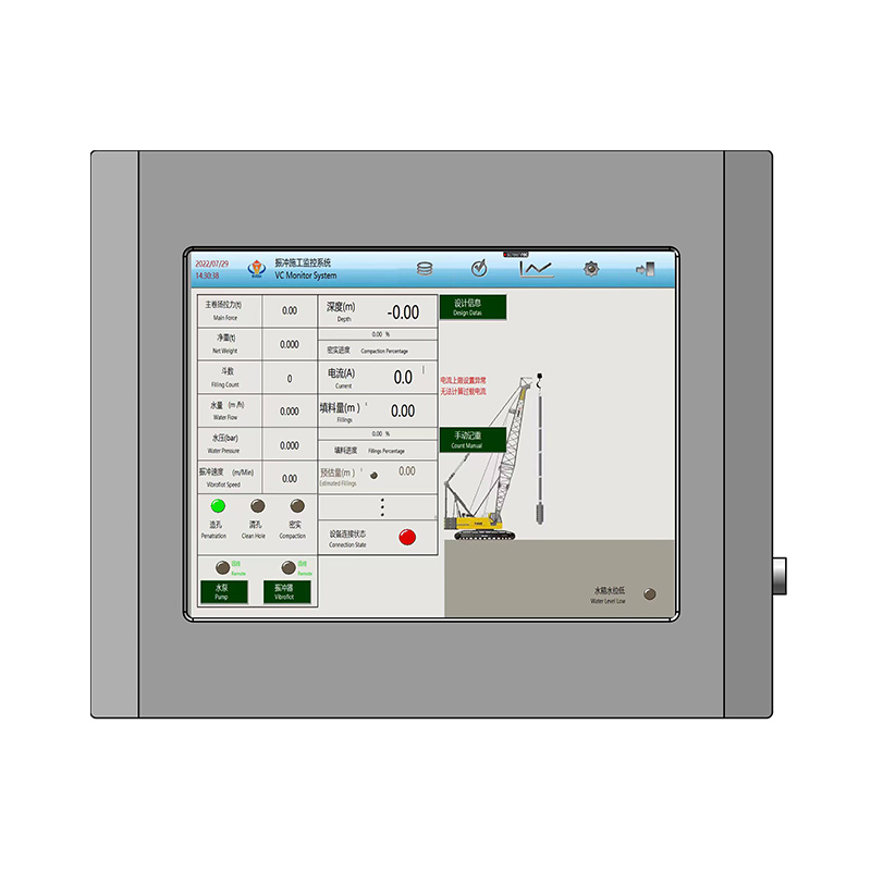
While the core method of vibroflotation was developed over 80 years ago, modern deep ground improvement has shifted entirely from manual estimation to verifiable digital records. Today, automated data collection is a non-negotiable requirement for project sign-off and risk mitigation. Geotechnical failures in granular soils often stem from unverified soil densification. Relying solely on post-compaction testing, like Cone Penetration Testing (CPT) or Standard Penetration Testing (SPT), to confirm bearing capacity introduces severe delays and rework costs if compaction criteria are not met uniformly across the grid. Deploying a purpose-built vibroflotation data recorder bridges the gap between execution and quality assurance. It provides real-time, objective metrics that prove structural stability, validate deep compaction, and ensure strict contractual compliance.
Key Takeaways
Core Metrics: Continuous logging of depth, electrical current (amperage), time, and material volume forms the baseline of verifiable vibro-compaction and vibro-replacement.
Real-Time Quality Assurance: Immediate operator feedback allows for on-the-fly adjustments to penetration rates and compaction hold times, drastically reducing the need for post-treatment rework.
Compliance & Reporting: Automated data logging generates unalterable, timestamped records necessary for engineering approvals, proving enhanced soil stability and long-term liability protection.
Supplier Evaluation: Selecting the right hardware requires assessing sensor durability against high-frequency vibration, software integration capabilities, and the availability of localized technical support.
The Role of a Vibroflot Control Monitor System in Ground Improvement
Success in ground improvement requires continuous, objective documentation of the dynamic compaction process at every single grid point. Historically, operators relied on analog gauges to estimate soil resistance. These gauges bounced violently during operation, making accurate readings nearly impossible. Moving beyond analog gauges is now a strict requirement for guaranteeing enhanced bearing capacity. A modern vibroflot control monitor system replaces guesswork with hard data. It ensures that every compaction point meets the exact specifications outlined by the geotechnical engineer.
The architecture of a modern monitoring system consists of several integrated components working in unison. Probe-mounted sensors detect immediate environmental changes. Mast-mounted depth encoders track the physical location of the equipment. Inside the cabin, high-contrast displays provide the operator with real-time feedback. Centralized data loggers capture all this information simultaneously. This network of sensors communicates continuously, creating a seamless flow of information from the subsurface directly to the operator and the project manager.
Automated logging entirely eliminates human error in recording critical metrics. Operators no longer need to manually write down hold times or guess peak amperage spikes. The system records these variables automatically at high polling rates. This shift to automation ensures absolute data integrity. Geotechnical engineers evaluating deep compaction results require this level of precision. Unalterable digital records protect contractors from liability and prove that the ground improvement was executed flawlessly.
Primary Metrics: What a Vibroflotation Data Recorder Actually Measures
Understanding the specific data points collected during ground improvement is essential for quality control. Each metric provides a distinct piece of the puzzle regarding subsurface stability.
Vibroflot Depth and Current Monitoring
There is a direct, undeniable correlation between electrical current and soil density in granular soils. The vibroflot motor requires electricity to spin its eccentric weight. As the surrounding soil becomes denser, it exerts more physical resistance against the vibrating probe. To maintain its rotational frequency against this increased resistance, the motor must draw more electrical current. Therefore, amperage is the primary proxy for soil compaction. Vibroflot depth and current monitoring systems track these amperage spikes to confirm when target density is achieved.
Depth encoders play an equally critical role. They track the exact vertical position of the powerful vibrating probes in real-time. This allows the system to map density achievements to specific subsurface elevations. When compacting soils at greater depths, knowing exactly where an amperage spike occurred is vital. It proves that the entire soil column, from the bottom up, has been properly treated without leaving any loose, uncompacted zones. For instance, if a project requires a minimum bearing capacity of 150 kPa, the engineer might correlate this to a target motor current of 180 amps at a specific depth. The operator watches the screen to ensure this threshold is met before moving upward.
Interpreting the Compaction Curve
Field engineers rely on the visual representation of the data log, commonly referred to as the compaction curve. The vertical axis typically represents depth, while the horizontal axis tracks amperage and time. A successful compaction point displays a distinct pattern. As the probe descends, amperage remains relatively low. During the withdrawal phase, the operator holds the probe at specific intervals. The data log should show a sharp, sustained spike in amperage at each hold point, indicating the soil has reached maximum density. If the log shows flat or erratic amperage lines during the hold phase, it immediately alerts the site supervisor that the soil layer is not responding to treatment, prompting an immediate investigation into soil composition or equipment performance.
Penetration Rates and Time-at-Depth Intervals
A comprehensive recorder tracks descent speed, hold times at specific compaction stages, and withdrawal rates. Descent speed indicates the initial state of the soil and the effectiveness of the water or air jets. Hold times are critical because compaction does not happen instantly. The probe must remain at a specific depth long enough for the vibrational energy to propagate outward and rearrange the soil particles.
The withdrawal phase is arguably the most critical part of the process. As the vibroprobe is slowly raised towards the surface while vibrating, the recorder tracks the time-at-depth. This ensures the overlaying soil gradually sinks and the lowermost material is fully densified. If the operator pulls the probe up too quickly, the soil will not collapse properly, leaving dangerous voids. Time-stamped data proves absolute adherence to the engineer's specified compaction methodology.
Material Volume and Stone Consumption (Vibro-Replacement)
For stone column applications, the data requirements expand significantly. The recorder must track the volume of aggregate introduced at each depth interval. As the probe creates a cavity, stone is fed into the hole to compensate for the sinking overlaying soil. The system logs exactly how much stone is consumed at every vertical foot or meter.
When constructing stone columns, the feed method dictates how data is recorded. Top-feed systems rely on surface loaders dumping stone into the crater created by the probe. Here, volumetric tracking often relies on loader bucket counts correlated with depth. Bottom-feed systems are far more precise. They utilize a tremie pipe attached to the vibroflot, feeding stone directly to the tip. Bottom-feed recorders use hopper load cells to measure the exact weight of stone discharged at each depth interval. This weight is then converted to volume, providing a highly accurate profile of the stone column's diameter. This data is paramount for verifying column continuity. If a specific depth interval consumes very little stone, it indicates a potential necking issue where the column is too narrow. Conversely, excessive stone consumption might indicate bulging into very soft surrounding soils.
Fluid Pressure and Flow Rates (Water/Air Jetting)
Water or air jetting is frequently used to assist probe penetration. Monitoring the pressure and flow rates of these fluids is essential. High-pressure jets cut through dense layers, allowing the probe to reach the target depth efficiently.
Operators must balance water pressure against soil conditions. In dense sand, high pressure is required to break the soil matrix and allow the probe to sink. However, once the target depth is reached, the operator must reduce the water pressure or switch to air jetting during the compaction phase. If high water pressure is maintained during withdrawal, it creates a quick condition, preventing the soil particles from locking together. The data recorder logs these pressure changes, allowing supervisors to verify that the operator followed the correct jetting sequence and preventing the over-washing of fines.
Spatial Positioning (GPS/GNSS Integration)
Modern recorders integrate directly with GPS and GNSS positioning systems. Compaction points are generally arranged at specific gaps, typically 1.8 to 3.0m on square or triangular grids. Missing a point by even half a meter can leave a weak zone in the foundation.
GPS integration verifies that the actual compaction points match the designed grid spacing perfectly. The coordinates are logged alongside the depth and amperage data. This creates a comprehensive, three-dimensional map of the treated site.
Evaluating Vibroflot Construction Data Monitoring Solutions
Selecting the right monitoring equipment dictates the reliability of your quality control program. Hardware and software must align with the harsh realities of heavy construction.
Solution Categories
Contractors generally choose between standalone data loggers and fully integrated rig control systems. Standalone loggers are retrofitted onto existing equipment. They collect data but do not interfere with machine operations. Integrated systems communicate directly with the rig's internal computers, sometimes automating the withdrawal process based on real-time amperage readings.
Feature
Standalone Data Loggers
Integrated Rig Control Systems
Installation Complexity
Low to Moderate. Easily retrofitted on older rigs.
High. Often requires OEM factory installation.
Operator Intervention
Requires operator to manually read screens and adjust controls.
Can automate probe withdrawal based on target metrics.
System Cost
Lower initial investment.
Higher initial investment.
Data Export Flexibility
High. Usually designed to export standard CSV/PDF files.
Variable. Sometimes locked into proprietary software ecosystems.
Hardware Durability and Sensor Reliability
Vibroflotation is an inherently violent process. Equipment is subjected to continuous, extreme high-frequency vibration, heavy moisture, and abrasive dust. Standard commercial electronics will fail within hours on a vibro rig. Ruggedized components with IP67 or IP69K ratings are mandatory. These ratings ensure the enclosures are completely dust-tight and can withstand high-pressure water jets.
Sensor redundancy is another critical evaluation point for vibroflot construction data monitoring. If a depth encoder fails halfway through a column, the data for that point is ruined. High polling rates are also necessary. The system must capture data multiple times per second to accurately record brief amperage spikes that indicate peak density.
Sensor Selection for Extreme Environments
Choosing the right sensor technology prevents mid-project failures. For depth tracking, contractors must choose between wire-draw encoders and rotary encoders. Wire-draw encoders are simple but susceptible to snapping if debris hits the wire. Heavy-duty rotary encoders mounted directly to the mast winch offer superior reliability because they are enclosed and protected from flying aggregate.
Amperage sensors must utilize non-invasive current transformers (CTs) installed inside the electrical cabinet, completely isolated from the vibration of the probe itself. This isolation guarantees long-term accuracy. Furthermore, pressure transducers used for water jetting must feature stainless steel diaphragms to resist the abrasive nature of sandy water backflow.
Data Visualization and Operator Feedback Loops
The cabin interface is the bridge between the machine and the operator. It must provide intuitive, graphical representations of depth versus amperage. Operators do not have time to read complex spreadsheets while maneuvering heavy machinery. They need clear visual indicators, such as color-coded bar charts, to guide them in real-time.
The system's ability to set automated alerts is highly valuable. A supervisor can program target compaction thresholds into the interface. When the probe hits the required amperage at a specific depth, the screen flashes green, signaling the operator to begin the withdrawal phase. This immediate feedback loop prevents both under-compaction and time-wasting over-compaction.
Compliance Reporting and Export Capabilities
Data is only useful if it can be easily analyzed and presented. The software backend of a vibroflotation quality control monitor recorder must support seamless export formats. Look for systems that generate raw CSV files, formatted PDF reports, and specialized geotechnical data formats that integrate with standard engineering software.
Security is equally important. The data logs must be encrypted and tamper-proof. In the event of a structural failure years down the line, these records serve as your primary legal defense. If the data can be easily altered in a spreadsheet program, it loses its legal validity. Secure, unalterable logs provide essential contractual protection.
Implementation Risks and Mitigation Strategies
Deploying digital monitoring systems in heavy civil construction introduces specific operational risks. Identifying these challenges early allows for proactive mitigation.
Common Data Anomalies and Field Troubleshooting
Even with robust systems, field crews will encounter data anomalies. Recognizing these patterns quickly prevents the recording of invalid compaction points.
Data Anomaly
Potential Cause
Field Action Required
Sudden, unexplained drop in amperage during a hold phase.
Probe has encountered a soft clay lens or an underground void.
Extend hold time. If amperage does not recover, notify the geotechnical engineer to adjust grid spacing.
Depth reading freezes while the probe is visibly moving.
Debris jammed in the depth encoder or severed sensor cable.
Halt operation. Inspect mast-mounted encoder and cable routing. Clear debris or replace cable.
Erratic, jumping amperage readings without corresponding soil changes.
Loose electrical connection in the CT sensor or extreme voltage fluctuation from the generator.
Check generator output stability. Inspect connections inside the main electrical cabinet.
Stone consumption registers zero while hopper is emptying.
Load cell failure or jammed volumetric sensor.
Recalibrate hopper load cells. Check for physical obstructions in the stone feed tube.
Calibration Drift and Maintenance Protocols
Continuous, powerful vibration causes mechanical and electrical wear. Over time, this leads to sensor drift. A depth encoder might start registering 10 meters as 9.8 meters. An amperage sensor might lose its zero baseline. This calibration drift compromises the entire quality control process.
The mitigation strategy requires establishing strict, documented calibration schedules. Sensors must be checked against known physical baselines weekly or monthly. Furthermore, modern systems utilize self-diagnosing sensor networks. These networks alert the operator immediately if a sensor's output falls outside logical parameters, preventing the collection of corrupted data.
Operator Adoption and Interface Usability
Introducing complex digital systems to heavy machinery operators often meets resistance. Operators are accustomed to feeling the machine's vibrations and listening to engine RPMs. Forcing them to rely on a digital screen requires a shift in working habits.
Mitigate this by prioritizing systems with intuitive, low-friction user interfaces. The screens must be readable in direct sunlight and operable while wearing heavy work gloves. Comprehensive vendor-led training is also mandatory. Operators must understand not just how to push the buttons, but why the data matters to the success of the project.
Site Connectivity and Data Redundancy
Ground improvement projects frequently occur in remote locations with poor or non-existent cellular network coverage. Relying entirely on cloud-based data logging is a massive risk. If the network drops, the data could be lost forever.
Ensure the recorder features robust local storage. Solid-state drives or industrial-grade SD cards must capture every data point locally. Data transmission protocols must be resilient. Modern systems utilize edge computing, processing the raw sensor data directly inside the cabin logger before attempting transmission. This reduces the bandwidth required for cloud synchronization. Once the rig is moved back into an area with connectivity, or at the end of the shift, the local data automatically uploads to the central server without requiring manual operator intervention. If all wireless transmission fails, the system must support physical data extraction via encrypted USB drives.
Selecting a Reliable Vibroflotation Monitor Supplier
The hardware is only as good as the company standing behind it. Evaluating suppliers requires looking past the spec sheet and understanding their ability to support your field operations.
Overall Value Influencing Factors
Move beyond initial hardware costs to evaluate long-term operational efficiency and lifecycle value. A cheap data logger that breaks down weekly will cost exponentially more in machine downtime and delayed project schedules. Evaluate the physical build quality, the warranty terms, and the expected lifespan of the primary sensors. A reputable vibroflotation monitor supplier will provide transparent data on mean time between failures for their components.
Technical Support and Integration Capabilities
Assess the supplier's ability to retrofit existing vibroflot equipment. Many contractors operate mixed fleets of varying ages and brands. The supplier must demonstrate the engineering capability to integrate their sensors seamlessly across your entire fleet, rather than just supplying OEM-integrated solutions for new rigs. Integration goes beyond just mounting sensors. The supplier must provide comprehensive wiring schematics that interface safely with the rig's existing power distribution.
Evaluate the availability of remote troubleshooting. When a system throws an error code on a remote site, you cannot wait three days for a technician to fly out. The supplier should offer remote diagnostic capabilities to identify the issue immediately. Additionally, they must have rapid hardware replacement programs to overnight critical parts to the job site.
Software Licensing and Updates
Clarify the long-term costs associated with data management software. Some suppliers lock you into expensive annual subscription models just to access your own data. Others provide perpetual licenses with the hardware purchase. Understand the firmware update policies. As operating systems evolve and new export formats are required by engineers, your recorder must receive regular, seamless software updates to remain compliant.
Conclusion
A high-quality vibroflotation quality control monitor recorder is not an optional upgrade. It is a critical requirement for verifiable, risk-free ground improvement and guaranteed bearing capacity. Relying on analog gauges or operator intuition is no longer acceptable in modern geotechnical engineering. Decision-makers must prioritize systems that offer robust depth and current monitoring, tamper-proof reporting, and ruggedized hardware proven in high-vibration environments.
Compile your specific site requirements, including grid spacing, maximum depth targets, and soil types.
Identify the exact reporting standards and data export formats required by your project's geotechnical engineer.
Audit your current fleet to determine if you need standalone retrofits or fully integrated rig control systems.
Q: What is the most critical data point tracked during vibro-compaction?
A: The most critical data point is the electrical current (amperage) drawn by the vibroflot motor. There is a direct correlation between this amperage and the resulting soil density. As granular soils densify, they resist the vibrating probe, forcing the motor to draw more current to maintain frequency. This spike confirms bearing capacity at specific depths.
Q: How does a vibroflotation quality control monitor recorder prevent rework?
A: It provides real-time cabin displays that allow operators to ensure target resistance is met before withdrawing the probe. By confirming density on the fly, operators eliminate the risk of failing post-compaction tests (like CPT), which would otherwise require moving the rig back to re-treat the area.
Q: How does the data differ between compacting granular soils vs. vibro-replacement?
A: Pure vibro-compaction relies heavily on amperage and time-at-depth to verify the densification of existing soils. Vibro-replacement (stone columns) requires all of those metrics plus the strict tracking of stone or aggregate volume consumption to ensure the constructed column has a consistent diameter.
Q: Can existing equipment be retrofitted with vibroflot construction data monitoring?
A: Yes. Specialized suppliers provide standalone data loggers, aftermarket depth encoders, and ruggedized sensors that can be installed on older rigs. This allows contractors to upgrade their legacy fleet to meet modern digital reporting standards without buying entirely new machinery.
Q: How is stone consumption measured in vibro-replacement data logs?
A: Stone consumption is typically measured using hopper load cells or volumetric tracking sensors. This data is integrated with the depth encoder readings to ensure a consistent volume of aggregate is placed at every vertical interval as the overlaying soil sinks.
Q: What should I include in a vibroflotation data monitoring inquiry?
A: You should include your specific rig type, maximum treatment depth, typical grid spacing (e.g., 1.8 to 3.0m), required export formats (CSV, PDF), and any specific geotechnical compliance standards mandated by your local engineering authorities.
Q: How often do vibroflot depth and current monitoring sensors need calibration?
A: Due to extreme vibrational wear, sensors typically require calibration checks monthly, or at the start of every new major project. Strict adherence to industry calibration guidelines ensures the data remains legally valid and technically accurate.