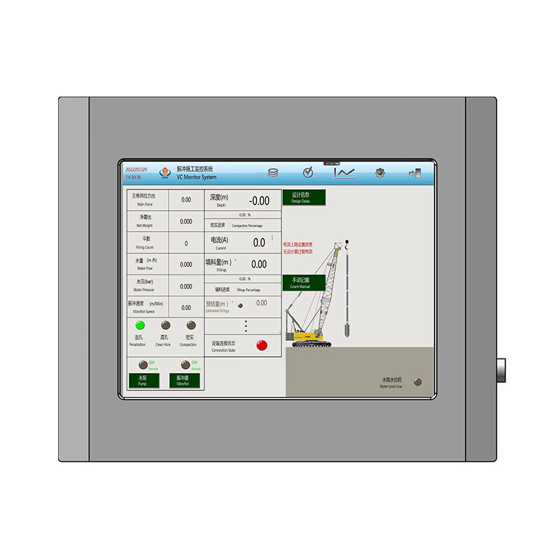
Deep foundation work carries inherent risk. Once ground improvement finishes, the results remain buried and invisible to the naked eye. Vibroflotation effectively rearranges soil particles at considerable depth using vibration combined with water or air pressure. However, verifying that stabilization demands rigorous oversight. Relying solely on theoretical design or superficial contractor assurances leaves projects vulnerable to differential settlement, structural failure, and severe liability. Verifying soil compaction requires a two-pronged approach. You need real-time equipment monitoring alongside rigorous post-installation testing. We evaluate these methodologies to ensure structural integrity and strict code compliance. Field engineers cannot just assume the soil reached the target density. You must prove it with hard data. This guide breaks down exactly how to track probe metrics during installation and validate those numbers with penetration tests weeks later.
Real-Time Data is Non-Negotiable: Continuous monitoring via automated data recorders prevents localized compaction failures before the rig even moves to the next point.
Post-Installation Verification: Relying on a combination of Cone Penetration Testing (CPT) and Standard Penetration Testing (SPT) provides the empirical evidence required for structural sign-off.
Method Matching: Testing protocols must be specifically adapted to the improvement type—vibro-compaction (granular soils) requires different acceptance criteria than vibro-replacement (stone columns), and top-feed methods require different monitoring than bottom-feed methods.
Contractor Accountability: Transparent, unalterable data logs are the primary defense against subpar execution by a ground improvement contractor.
The Framework for Ground Improvement Quality Control
Defining geotechnical success criteria before construction begins dictates the trajectory of the entire project. Engineers must establish baseline soil metrics prior to mobilizing heavy equipment. A thorough subsurface soil analysis confirms vibroflotation feasibility. This initial investigation identifies soil stratigraphy, groundwater levels, and particle size distribution. Clean sands respond exceptionally well to simple vibration. Silty or cohesive soils require stone column installation to achieve the desired bearing capacity. You cannot apply a one-size-fits-all approach to soil mechanics.
Design engineers set specific relative density targets based on structural loads. They calculate the exact bearing capacity requirements for the proposed facility. These theoretical targets mean nothing without practical field calibration. Pre-construction test programs bridge the gap between design and execution. Contractors develop detailed method statements outlining their proposed equipment and procedures. They then execute these methods in designated trial areas on the actual site to prove their equipment can hit the required numbers.
Trial areas allow engineers to calibrate equipment and finalize grid spacing. Teams test different compaction point patterns, usually triangular or square grids. They evaluate the effectiveness of top-feed versus bottom-feed delivery methods. Engineers conduct penetration tests before and after the trial compaction. Comparing these results establishes site-specific pass/fail thresholds. This empirical data dictates the production parameters for the entire site.
Setting up a proper trial area involves several strict phases:
Select a representative 20-meter by 20-meter section of the site that reflects the worst-case soil conditions found in the initial geotechnical report.
Perform baseline Cone Penetration Tests (CPT) to establish the exact pre-improvement relative density of the soil layers.
Install compaction points using varying grid spacings, such as 2.5-meter, 3.0-meter, and 3.5-meter intervals, to determine the maximum effective radius of the probe.
Wait the required pore pressure dissipation period, then perform post-improvement CPTs directly in the center of the grid patterns to measure the densification.
Analyze the data to select the most efficient grid spacing that still meets the minimum bearing capacity requirements.
Implementing rigorous ground improvement quality control prevents catastrophic project failures. The consequences of inadequate verification compound rapidly. Discovering poor compaction during the foundation pouring phase destroys construction schedules. Remediation at this stage requires removing poured concrete and mobilizing specialized micro-piling rigs. Project overruns escalate immediately when heavy machinery has to return to a site that was supposedly finished.
Long-term risks carry even heavier consequences. Post-construction differential settlement cracks foundations and misaligns structural steel. Facilities experience compromised operational capacity. Legal liabilities mount as building owners pursue damages for structural failure. Safety risks to building occupants remain entirely unacceptable. Upfront investment in rigorous testing frameworks eliminates these downstream liabilities and provides a permanent record of structural competence.
Real-Time Monitoring: Vibroflotation Construction Data
Modern vibroflot probes operate as sophisticated data collection instruments. They feature onboard computers that log continuous data during the penetration and compaction phases. Automated data collection completely outperforms manual operator logs. Manual logging introduces human error and allows for intentional data manipulation. A dedicated vibroflot data recorder captures every variable at sub-second intervals. This creates an unalterable digital footprint of the entire compaction process.
Equipment calibration drives data accuracy. Contractors utilize either electrically or hydraulically powered probes. These systems generate different energy outputs and resistance signatures. Electric probes measure resistance via amperage draw. Hydraulic probes measure resistance through hydraulic fluid pressure. Geotechnical engineers must calibrate their data expectations based on the specific power source utilized on site. A 130kW electric probe will show a completely different baseline amperage in the air compared to a 180kW probe.
Tracking key metrics during installation ensures proper energy transfer into the soil matrix. Amperage or power consumption serves as the primary indicator of success. As the eccentric weight inside the probe spins, it creates horizontal vibrations. The surrounding soil densifies and resists this movement. The probe's motor draws more current to maintain its operational frequency. This electrical or hydraulic spike serves as a direct proxy for soil density. It confirms particle rearrangement in real time. When the amperage hits the target threshold, the operator knows that specific depth interval has reached maximum compaction.
Depth verification and hold times require strict, continuous monitoring. The probe must reach the required considerable depth to treat the full soil profile. Operators track the exact elevation of the probe tip. They also record the duration of compaction at each specific depth interval. Insufficient hold times fail to transfer enough energy to densify the surrounding soil. Operators typically hold the probe at each 0.5-meter depth interval for 30 to 60 seconds. The data logger records these intervals automatically, preventing operators from rushing the process to finish their shift early.
Air and water pressure monitoring dictates the success of the flushing process. Flush pressure requirements vary entirely by installation method. Top-feed systems rely on high-volume water pressure to keep the borehole open. Bottom-feed systems utilize compressed air to deliver stone through a tremie pipe. Monitoring these pressures prevents borehole collapse and ensures continuous material flow. Tracking the exact tonnage of backfill material used remains mandatory. This volume tracking drives accurate vibroflotation construction data analysis, confirming column continuity and preventing necking in the stone column.
In-situ penetration testing validates the real-time construction data. Cone Penetration Testing (CPT) provides continuous, highly accurate soil profiling. Operators push an instrumented cone into the ground at a constant rate. The cone measures tip resistance and sleeve friction simultaneously. This provides a high-resolution profile of relative density in granular soils across the entire treated depth. CPT eliminates the subjective nature of manual soil sampling. The data feeds directly into a computer, generating a continuous graph of soil strength from the surface down to the refusal depth.
Standard Penetration Testing (SPT) applies primarily to mixed soils or highly gravelly conditions. Operators drive a split-barrel sampler into the soil using a standardized 140-pound drop hammer falling 30 inches. They record the number of blows required to advance the sampler the final 12 inches of an 18-inch drive. Engineers correlate these blow counts to bearing capacity improvements. While less continuous than CPT, SPT allows for physical soil recovery. Engineers can visually classify the soil and send samples to the lab for fines content analysis.
Timing heavily influences test accuracy. Engineers mandate a specific waiting period between vibroflotation and penetration testing. The vibration process temporarily increases pore water pressure in saturated soils. This reduces effective stress and makes the soil appear weaker than its actual densified state. The waiting period allows for pore water pressure dissipation. This typically takes one to three weeks depending on soil permeability. Testing too early yields false failures and forces contractors to perform unnecessary rework.
Stone columns require specific load testing protocols to verify structural performance. Plate Load Tests (PLT) verify the stiffness of individual stone columns. Technicians place a rigid steel plate, usually 0.5 to 1.0 meters in diameter, over the column head. They apply incremental loads using hydraulic jacks reacting against a heavy steel frame anchored to the ground. Dial gauges measure the corresponding settlement. This confirms the ultimate bearing capacity of the isolated column and ensures it can handle the concentrated loads of the building footings.
Zone Load Tests evaluate macro-settlement behavior under simulated structural loads. This method tests a group of columns and the surrounding matrix soil simultaneously. Technicians construct a large concrete pad over multiple compaction points. They apply massive loads using stacked concrete blocks or large water tanks. They load the pad up to 150% of the design working load. This test provides the most accurate representation of how the improved ground will perform under the actual building footprint. It measures the composite interaction between the rigid stone columns and the softer native soil.
Geophysical testing methods offer valuable supplementary data. Crosshole Seismic Testing measures shear wave velocity between two boreholes. Soil stiffness correlates directly with the speed of these seismic waves. This non-destructive method serves as an excellent indicator of overall ground improvement, especially in soils where penetration tests are difficult. Comprehensive vibroflotation acceptance testing integrates these physical and geophysical methods. It forms the empirical backbone of reliable vibroflotation quality testing.
Evaluating Testing Methodologies: Trade-offs and Scalability
Balancing execution speed and data reliability challenges every geotechnical project manager. Zone Load Tests provide the most accurate macro-level behavioral data available. However, they require massive mobilization efforts and weeks of setup time. They halt construction in the immediate test area. Conversely, CPTs deliver rapid, scalable data. A single CPT rig can execute dozens of soundings in a single day, providing immediate feedback to the engineering team. Engineers must balance these trade-offs when designing the testing program.
Determining the appropriate frequency of testing depends entirely on project risk profiles. Local building codes often dictate absolute minimums. Testing one in every fifty columns suits low-risk structures like single-story warehouses. High-risk facilities, such as power plants or high-rise towers, demand tighter oversight. These projects may require testing one in every twenty columns. The testing frequency must align with the acceptable tolerance for differential settlement. If the structure houses sensitive manufacturing equipment, the testing frequency must increase to guarantee zero movement.
Adapting tests to soil variability prevents wasted effort and skewed data. Certain tests face severe limitations based on underlying soil stratigraphy. Dense gravel layers or large cobbles frequently cause CPT refusal. The delicate cone cannot penetrate these obstructions without sustaining damage. Engineers must switch to SPT or heavy dynamic probing in these specific zones. Rigid adherence to a single testing method often stalls progress. Field teams must have the authority to pivot their testing strategy when they encounter unexpected subsurface conditions.
The presence of cohesive soil layers dictates a complete shift in acceptance criteria. Density-based metrics lose relevance in clay-heavy soils. Vibroflotation cannot densify cohesive soils through vibration alone. Instead, the process installs rigid stone columns to reinforce the soft matrix. Teams must focus on stiffness, consolidation metrics, and area replacement ratios. This adaptability ensures accurate stone column quality control regardless of subsurface variations.
Comparison of Ground Improvement Verification Methods
Testing Method
Primary Application
Data Yield
Setup Requirements
Execution Speed
Cone Penetration Testing (CPT)
Clean sands, silty sands
Continuous tip resistance and friction
Minimal (Truck-mounted rig)
Very Fast
Standard Penetration Testing (SPT)
Mixed soils, gravelly sands
Discrete blow counts, soil samples
Moderate (Drill rig required)
Moderate
Plate Load Test (PLT)
Individual stone columns
Stiffness, localized bearing capacity
Heavy (Reaction frame, jacks)
Slow
Zone Load Test
Column groups and matrix soil
Macro-settlement behavior
Massive (Concrete pad, kentledge)
Very Slow
Crosshole Seismic
All soil types
Shear wave velocity, stiffness
Moderate (Cased boreholes)
Moderate
Implementation Risks in Quality Verification
Identifying data manipulation protects the structural integrity of the project. Falsifying manual logs remains a persistent threat on poorly managed sites. Operators facing tight deadlines may fabricate hold times or depth achievements to hit their daily production quotas. Miscalibrated data recorders also generate dangerous false positives. The system might record high amperage spikes due to mechanical friction in the rig rather than actual soil resistance. Engineers must cross-reference real-time construction data with post-installation CPT results. Discrepancies between the digital logs and the physical soil profile highlight potential execution flaws.
Vetting your ground improvement contractor requires strict, uncompromising criteria. Evaluate their quality control infrastructure before signing contracts. Demand the use of proprietary, encrypted data loggers that prevent manual editing. Require the contractor to maintain an independent QA/QC engineer on staff who reports directly to the project owner, not the site foreman. Ensure they match the correct probe technology to your specific soil profile. Electrical and hydraulic probes behave differently in varying geologies. A mismatch results in inadequate energy transfer and failed compaction.
Watch for these specific red flags when reviewing contractor data:
Perfectly uniform hold times across varying soil strata, indicating the operator is ignoring the amperage feedback and just running a timer.
Amperage spikes that occur instantly upon reaching a depth interval, rather than building gradually as the soil densifies.
Stone consumption volumes that do not match the theoretical volume of the installed columns, indicating necking or borehole collapse.
Refusal to provide raw, unedited data files from the onboard computer systems.
Handling non-compliant test results demands clear standard operating procedures. When a penetration test or load test fails, immediate action follows. Project managers must avoid the temptation to average out failing grades with passing ones from adjacent areas. Localized re-compaction often solves minor density deficiencies. The rig returns to the failing coordinate, penetrates to the weak zone, and re-drives the probe. Installing additional intermediate compaction points reinforces weak zones effectively. Severe, widespread failures may require revising foundation designs entirely, shifting from shallow footings to deep piles.
Conclusion
Audit your current project specifications to mandate automated, encrypted data loggers on all vibroflot rigs.
Write specific testing frequencies and waiting periods directly into your site agreements before mobilization.
Hire an independent geotechnical engineer to design a site-specific testing program tailored to your soil stratigraphy.
Establish clear, contractual remediation protocols for handling non-compliant penetration or load test results.
FAQ
Q: What is the standard waiting period before conducting vibroflotation acceptance testing?
A: The standard waiting period ranges from 7 to 21 days. Vibroflotation temporarily increases pore water pressure in saturated soils, which reduces effective stress. Testing immediately yields artificially low density readings. Waiting allows the pore pressure to dissipate, revealing the true stabilized strength of the soil.
Q: How does a vibroflot data recorder measure soil compaction?
A: The recorder tracks the resistance the probe encounters. As the surrounding soil densifies, it restricts the probe's horizontal vibration. The probe's motor must draw more electrical current or hydraulic pressure to maintain its frequency. The recorder logs these energy spikes as a direct proxy for soil density.
Q: What is the difference between vibro-compaction and vibro-replacement testing?
A: Vibro-compaction testing focuses on relative density in clean sands, typically using continuous Cone Penetration Testing. Vibro-replacement testing evaluates the structural integrity of installed stone columns in cohesive soils. This requires Plate Load Tests or Zone Load Tests to measure stiffness and macro-settlement behavior.
Q: How does the installation method (top feed vs. bottom feed) affect quality control data?
A: Top-feed methods require monitoring high-volume water flush pressure and surface material consumption. Bottom-feed methods require monitoring compressed air pressure and the precise volume of stone delivered through the internal tremie pipe. The data logger must be calibrated to track the specific delivery mechanism used.
Q: How many stone columns should be tested for quality control?
A: Industry standards typically require testing 1% to 5% of the total installed stone columns. The exact percentage depends on local building codes, soil variability, and the structural loads of the proposed facility. High-risk structures demand higher testing frequencies to ensure absolute stability.
Q: Can Standard Penetration Testing (SPT) be used for all ground improvement verification?
A: No. While SPT works well in mixed or highly gravelly soils, it only provides discrete data points at specific intervals. Cone Penetration Testing is generally preferred for clean sands because it provides a continuous, high-resolution profile of soil resistance without the subjectivity of manual blow counts.
Q: What happens if a vibroflotation test fails?
A: If a test fails, engineers implement predefined remediation steps. This usually involves re-driving the vibroflot probe at the failing coordinate to apply additional energy. If the zone remains weak, contractors install supplementary intermediate stone columns to bridge the gap and achieve the required bearing capacity.