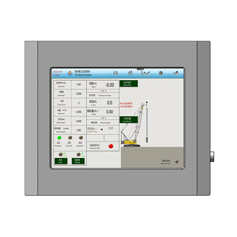
Deep foundation projects carry immense operational stakes. Subsurface uncertainties easily compromise structural integrity. Ground improvement techniques like vibro-compaction and vibro-replacement demand absolute precision. Relying on blind execution creates severe engineering risks. Manual operator estimation leads to inconsistent soil bearing capacities. It causes heavy material waste and ultimately results in failed load tests. You cannot afford guesswork when stabilizing soil for massive infrastructure. You need a reliable solution to bridge geotechnical engineering specifications with on-site execution. A modern vibroflot control system transforms subjective operation into verifiable, data-driven quality control. It guarantees every compaction point meets strict design standards. By digitizing the entire process, site managers gain real-time visibility into subsurface conditions. This technology eliminates human error and ensures uniform ground treatment across the entire job site.
Key Takeaways
Core Metrics Dictate Quality: Effective systems must simultaneously track depth, amperage, flush pressure, and stone consumption to guarantee soil compaction and column integrity.
Hardware Reliability is Non-Negotiable: The vibroflot electrical control cabinet must withstand extreme vibration, dust, moisture, and direct sunlight inherent to geotechnical job sites.
Data Integrity Drives Compliance: A reliable vibroflot process data recorder automates reporting and utilizes unique database identifiers to ensure absolute traceability and prevent data compromise.
Vendor Support Mitigates Downtime: Selecting a vibroflot control system manufacturer requires evaluating their ongoing vibroflotation monitoring support service, not just upfront hardware costs.
The Strategic Role of a Vibroflot Control System in Ground Improvement
Ground improvement success relies entirely on measurable outcomes. Engineers look for specific target relative densities when treating cohesionless soils like loose sands and gravels. They demand continuous stone column diameters to mitigate soil liquefaction risks in active seismic zones. Monitoring systems validate these outcomes in real-time. Without accurate telemetry, you cannot prove the soil matrix achieved the required load-bearing capacity. The control system acts as the definitive source of truth for site engineers, inspectors, and project owners.
Legacy methods fall dangerously short of modern engineering standards. Older rigs rely on manual stopwatches and visual amperage dials that bounce erratically during operation. Operators make physical chalk marks or spray paint lines on the mast to estimate depth. Automated systems replace this outdated guesswork with highly precise, sensor-driven data logging. Digital sensors capture hundreds of data points per second. This provides a granular view of the compaction process that human observation simply cannot match. You get a complete digital footprint of the entire probe penetration and withdrawal cycle.
Continuous monitoring actively prevents catastrophic construction errors. It stops premature probe withdrawal, which is the leading cause of necking in stone columns. It ensures sufficient compaction time at every specific depth interval. You avoid dangerous probe deviation and guarantee uniform ground treatment across the entire grid. When operators see real-time data on their screens, they make immediate corrections. This proactive risk mitigation prevents costly rework and keeps the project timeline intact. We see this constantly on sites with highly variable soil strata. One section might require three minutes of compaction per meter, while another requires five. Manual estimation fails here. Data-driven execution adapts instantly to the changing subsurface conditions.
The influence zone around the vibrator tip requires specific energy inputs to achieve densification. If the operator pulls the probe up too quickly, the energy does not transfer adequately into the surrounding soil. The monitoring system tracks this energy transfer by correlating time, depth, and motor current. This ensures the radial compaction meets the geotechnical design parameters before the operator is permitted to move to the next depth interval.
Core Metrics Every Vibroflot Control Monitoring System Must Track
A comprehensive vibroflot control monitoring system must capture a specific set of operational metrics. These data points collectively paint a complete picture of subsurface soil behavior and equipment performance.
Amperage and Power Consumption
Motor current acts as the primary proxy for soil resistance. As the vibroflot densifies the surrounding soil, friction against the probe increases. This forces the electric motor to draw more current to maintain its eccentric weight rotation and vibration frequency. Higher amps directly indicate denser soil compaction. You must set automated thresholds for peak amperage within the system. This automated alert signals exactly when target compaction is achieved at a specific depth. Operators watch the amp curve flatten out on their display, indicating the soil has reached maximum density for that specific energy input.
Depth and Penetration Rate
Knowing the exact location of the vibroflot tip is non-negotiable. Rotary encoders or heavy-duty wire-draw sensors mount directly to the rig mast to track depth down to the centimeter. Penetration and withdrawal rates directly impact the surrounding soil matrix. Moving the probe too fast leaves loose, uncompacted pockets. Moving too slowly wastes valuable operational time and burns unnecessary diesel. The monitoring system ensures the operator maintains the optimal vertical speed prescribed by the site engineer.
Flush Media Pressure and Flow (Air/Water)
High-pressure water or compressed air jets the probe into the ground, breaking surface tension and clearing displaced soil. Monitoring this flush media pressure keeps operations smooth and prevents equipment damage. Pressure drops or sudden spikes indicate severe blockages at the probe tip. They also signal a sudden loss of flush media or unexpected changes in soil strata. Tracking flow rates helps operators adjust their approach when hitting dense clay layers versus loose, permeable sand.
Stone Feed Rate and Volume (For Vibro-Replacement)
Vibro-replacement builds structural stone columns underground using either top-feed or bottom-feed methods. This requires meticulous monitoring of stone backfill quantities. Tracking the exact volume of stone deposited per depth interval ensures a uniform column diameter. Systems integrate seamlessly with hopper load cells, skip bucket counters, or pressure sensors on the feed tube. If the stone feed rate drops while the probe withdraws, the column will neck or collapse, leading to a direct failure during load testing.
Probe Tilt and Verticality
Maintaining a straight vertical path ensures structural stability and prevents the probe from drifting into adjacent column zones. Heavy-duty dual-axis inclinometers monitor the probe alignment in real-time. They ensure the equipment remains within acceptable vertical deviation tolerances. These tolerances typically stay strictly below 1-2%. Excessive tilt compromises the load-bearing capacity of the finished stone column and puts severe mechanical stress on the extension tubes.
To ensure complete compaction coverage, field teams follow a strict operational sequence monitored by the system:
Position the rig precisely over the surveyed compaction point using integrated GPS coordinates.
Activate the flush media to break surface tension and begin the initial penetration phase.
Monitor the depth encoder as the probe reaches the target design depth specified in the plans.
Observe the amperage spike as the probe hits the dense bearing stratum at the bottom of the hole.
Begin the step-by-step withdrawal process, holding at specific intervals until peak amperage is achieved.
Record the total stone volume consumed during the upward pass to verify column integrity.
Export the completed column data to the central database before moving to the next grid point.
Operational Metric
Primary Sensor Type
Engineering Purpose
Failure Consequence if Unmonitored
Motor Amperage
Current Transformer (CT)
Measures soil resistance and compaction density.
Loose soil lenses, failed load tests, settlement.
Probe Depth
Rotary Encoder / Wire-Draw
Tracks vertical position and withdrawal speed.
Incomplete column length, premature withdrawal.
Flush Pressure
Pressure Transducer
Detects tip blockages and soil strata changes.
Probe getting stuck, burned out water pumps.
Stone Volume
Hopper Load Cells
Ensures continuous stone column diameter.
Column necking, structural collapse under load.
Verticality
Dual-Axis Inclinometer
Prevents probe deviation and column tilt.
Off-center columns, bent extension tubes.
Hardware and Infrastructure: Evaluating the Vibroflot Electrical Control Cabinet
Geotechnical sites expose sensitive equipment to brutal environmental conditions. A rugged vibroflot electrical control cabinet forms the backbone of the entire monitoring operation. It must feature high Ingress Protection ratings. IP65 or IP67 protection is mandatory. This shielding protects delicate internal electronics from corrosive marine environments, heavy rain, and highly abrasive construction dust. We have seen standard commercial cabinets fail within weeks on coastal reclamation projects due to salt fog ingress shorting out the terminal blocks.
Outdoor operation presents severe physical visual challenges for rig operators. Human-Machine Interface displays need high-nit brightness capabilities to cut through the glare. Anti-glare coatings are essential for readability. Physical sun shades help operators read screens accurately in direct, blinding sunlight. If the operator cannot read the screen, the entire monitoring system becomes useless, forcing them to revert to manual guesswork.
Vibroflotation rigs generate constant low-frequency, high-amplitude vibrations. These vibrations destroy standard electrical panels. Internal components like Programmable Logic Controllers, relays, and Variable Frequency Drives must feature heavy-duty shock mounts. Proper vibration isolation prevents catastrophic mechanical failure and disconnected internal wiring. The cabinet itself is often mounted on rubber isolators to dampen the kinetic energy transferring from the power pack.
Modern control cabinets utilize VFDs to adjust vibroflot frequency dynamically. Different soil types require different vibration frequencies for optimal compaction. The control system must interface seamlessly with these drives. It sends precise commands to alter motor speed based on real-time soil feedback. However, VFDs generate significant heat. Since the cabinet is sealed against dust and water, it requires internal heat sinks and closed-loop circulation fans to prevent the electronics from overheating during long summer shifts.
Site power is notoriously unreliable. Generator failures happen frequently on remote construction sites. Systems need robust manual override capabilities and physical emergency stops. Uninterruptible Power Supplies prevent critical data loss during sudden electrical outages. Redundancy ensures you never lose a day of compaction data just because a generator ran out of diesel.
Data Management: The Role of the Vibroflot Process Data Recorder
The rig operator requires immediate, clear visual feedback to execute the job. The HMI screen displays real-time visual graphs plotting depth against motor amperage. Target lines and flashing alarms prompt immediate operational adjustments. This interface must be highly intuitive. Complex, cluttered screens overwhelm operators and lead to poor decision-making. The display should focus strictly on the active depth interval, current amperage, and remaining stone volume.
Data integrity requires strict, immutable database structures. Assigning public-facing unique keys to every single compaction point ensures absolute traceability. This architecture prevents accidental data overwriting or site mix-ups. When a load test fails, engineers trace the exact column back to its unique digital signature to investigate the root cause. They can see exactly who operated the rig, what time the column was built, and the precise amperage achieved at the failure depth.
Back-office engineers rely heavily on this structured data. A vibroflotation quality control data monitor verifies that every point meets geotechnical design specifications. It removes subjective guesswork from quality assurance. Engineers review the compaction logs remotely, approving sections of the site for subsequent construction phases without needing to drive out to the field.
Regulatory compliance demands specific reporting formats. A reliable vibroflot process data recorder must generate tamper-proof exports. PDF reports, raw CSV files, and standardized AGS formats are strictly necessary. The AGS format is particularly important because geotechnical engineers import this data directly into 3D modeling software like Plaxis or AutoCAD Civil 3D. These exports facilitate smooth client handovers and satisfy rigorous third-party geotechnical audits.
Next-Generation Capabilities: AI and Predictive Analytics
Cutting-edge control systems now utilize historical data retrieval architectures. They actively compare real-time soil resistance against past successful projects stored in the cloud. This allows the system to optimize vibration frequency and compaction time on the fly. By leveraging historical telemetry, contractors reduce the time spent on each compaction point without sacrificing quality. The system learns the specific behavioral profile of the site's soil and adjusts the target parameters to maximize efficiency.
Continuous monitoring establishes a clear baseline for equipment performance. Tracking amperage draws and vibration anomalies alerts operators to impending mechanical failures. Predictive maintenance schedules replace reactive repairs. You swap out worn bearings, leaking hydraulic hoses, or failing motors before a catastrophic breakdown halts site operations. This data-driven maintenance approach keeps the rig running continuously, protecting the project schedule.
How to Evaluate a Vibroflot Control System Manufacturer
Hardware compatibility is a major evaluation factor. Assess whether the system is agnostic or proprietary. Agnostic systems can be retrofitted to older rigs or different equipment brands. Proprietary systems lock you into a single hardware ecosystem. An open architecture provides greater fleet flexibility and extends the lifespan of your existing machinery. You want a system that works just as well on a twenty-year-old crane-suspended rig as it does on a brand-new excavator-mounted unit.
Hardware is only part of the equation. You must evaluate the vibroflot control system manufacturer based on their technical support network. A strong vibroflotation monitoring support service ensures rapid remote troubleshooting. It guarantees seamless software updates and rapid on-site technician availability when hardware fails. If a sensor goes down, you need a replacement shipped overnight, not next month.
Modern manufacturers offer dedicated cloud-based dashboards. General contractors and project owners log in securely. They view real-time ground improvement progress across the entire site. This transparency streamlines stakeholder relationships. It builds immense trust between the geotechnical contractor and the client, as they can watch the ground improvement grid turn green point by point.
Implementation Risks and Mitigation Strategies
Harsh site conditions inevitably cause sensors to drift over time. You must implement a mitigation strategy centered on strict, documented calibration schedules. Regular physical checks maintain data accuracy. If the depth encoder drifts by a few inches, the entire compaction log becomes invalid. Field crews must verify the digital depth reading against physical markings on the mast at the start of every single shift.
Geotechnical records are highly sensitive documents. Encrypted data transmission from the rig to the cloud prevents unauthorized access. It stops spoofing or fraudulent alteration of compaction logs by malicious actors. Secure data pipelines ensure the integrity of your final engineering reports. You cannot risk a scenario where compaction data is manipulated to cover up poor field execution.
Introducing digital systems to veteran operators causes inevitable friction. They are accustomed to manual methods and physical intuition. We recommend phased training programs. Pair this with highly intuitive HMI design to ensure rapid operator buy-in. When operators see how the system makes their job easier and prevents them from having to redo failed columns, resistance fades quickly.
Sensor cables risk snapping during heavy operation. Heavy machinery easily crushes exposed wires on the ground. Armored cabling, such as steel-braided polyurethane, is an absolute necessity. Wireless sensor options effectively mitigate this physical risk by removing the vulnerable cable runs entirely, transmitting data from the mast directly to the cabin via secure radio frequencies.
Conclusion
Audit your current rig fleet to identify manual monitoring vulnerabilities and outdated sensor hardware.
Define your specific geotechnical reporting requirements based on local regulatory standards and client demands.
Request a technical demonstration from a specialized manufacturer to test HMI usability and software integration.
Establish a strict sensor calibration schedule for all active equipment before deploying to a new job site.
FAQ
Q: What is the most important metric to monitor during vibro-compaction?
A: Motor amperage is the most critical metric. It serves as a direct proxy for soil resistance. As the vibroflot compacts the surrounding soil, resistance increases, causing the motor to draw more current. Hitting peak amperage targets confirms optimal soil density.
Q: Can a vibroflot control monitoring system be retrofitted to older rigs?
A: Yes, agnostic systems can upgrade legacy equipment. The process involves installing independent depth, pressure, and amperage sensors directly onto the older rig. A new electrical control cabinet is then wired to these sensors to digitize the manual operation.
Q: How does a vibroflot process data recorder prevent fraudulent reporting?
A: It utilizes automated, time-stamped, and encrypted data logging. By assigning unique database keys to each compaction point, the system removes manual data entry. This architecture creates an immutable record that prevents tampering or fraudulent alteration of geotechnical results.
Q: What is the difference between vibro-compaction and vibro-replacement monitoring?
A: Vibro-compaction monitoring focuses primarily on depth, amperage, and compaction time to densify granular soils. Vibro-replacement builds stone columns, requiring additional monitoring for stone feed volume, hopper weight, and precise withdrawal intervals to ensure continuous column diameter.
Q: Why is flush water pressure monitored during vibroflotation?
A: Flush water jets the probe into the ground and clears displaced soil. Monitoring pressure detects blockages at the probe tip. Sudden pressure drops indicate a loss of flush media, while spikes suggest encountering dense, impenetrable soil strata.
Q: How often should vibroflot sensors be calibrated?
A: Sensors require calibration before every new project deployment. Harsh site vibrations and extreme temperatures cause electronic drift. Monthly verification checks against known physical benchmarks ensure depth encoders and pressure transducers maintain strict accuracy throughout the project lifecycle.