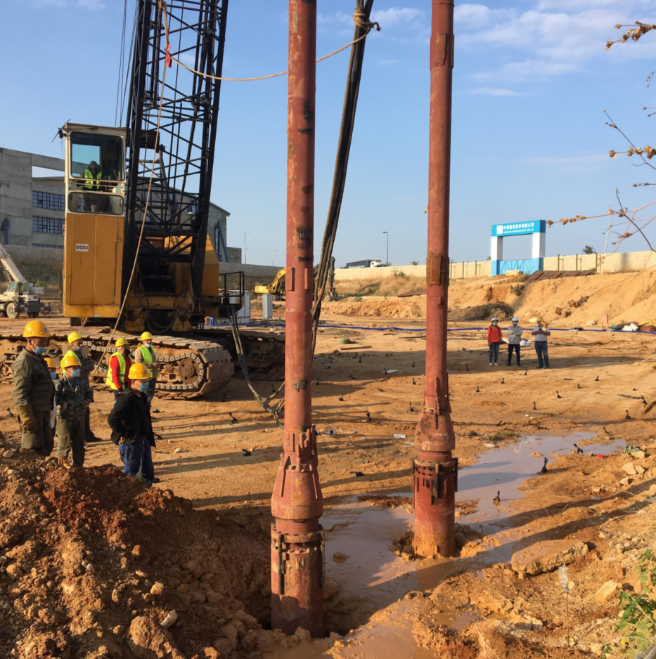
Large-scale liquid storage infrastructure exerts extreme static and dynamic loads on the ground. Facilities housing LNG, water, and oil demand uncompromising foundational stability. Heavy, flexible steel structures remain highly susceptible to differential settlement, edge shear failure, and shell deformation when built on loose or compressible soils. Engineers face a strict challenge. They must secure large structural footprints without overspending on deep foundations. We need structurally sound alternatives to driven piles. Implementing vibroflotation for tank foundations mitigates settlement risks and increases soil bearing capacity through deep vibratory compaction. The technique transforms the existing subgrade into a reliable load-bearing matrix. You will learn how this method addresses load distribution, soil suitability, equipment selection, and risk management to ensure long-term structural integrity.
Targeted Settlement Control: Vibroflotation mitigates both total and differential settlement, ensuring the structural integrity of the tank shell and piping connections.
Soil-Specific Application: Vibro compaction is highly effective for granular soils (sands and gravels with <10% fines), while vibro replacement (stone columns) adapts the method for mixed or cohesive soils.
Cost-to-Performance Ratio: Compared to deep pile foundations, vibroflotation significantly reduces material costs and project timelines while achieving required bearing capacities.
Equipment Criticality: Project success relies heavily on specifying the correct probe amplitude, frequency, and deployment method (top vs. bottom feed) from a verified ground improvement equipment manufacturer.
The Engineering Challenge of an Oil Storage Tank Foundation
Load Characteristics and Failure Mechanisms
Large-diameter storage tanks apply massive, uniform stress distributions to the underlying subgrade. A fully loaded 100,000-barrel tank acts as a massive flexible load, often exerting ground pressures between 150 and 250 kPa. The fluid weight pushes downward evenly, but the soil reacts unevenly based on its stratigraphy. We often see distinct differences between edge settlement and center settlement. This creates a "dishing" effect. The center of the tank settles deeper than the rigid perimeter.
Excessive dishing leads to shell buckling. It can also cause bottom plate rupture. The steel plates stretch and deform under the uneven support, stressing the welded seams. Tanks undergo continuous cyclic loading. Filling and emptying cycles create long-term soil fatigue. This dynamic action repeatedly alters pore water pressure within the subgrade. Over time, fluctuating pressures weaken the soil matrix, accelerating unexpected settlement. The annular ring, where the shell meets the floor, takes the brunt of these shear forces. If the soil yields here, the entire structure faces immediate operational failure.
Success Criteria for Tank Foundation Ground Improvement
Engineers must define strict technical benchmarks for a successful oil storage tank foundation. The primary metric involves specific allowable total settlement limits. Most structural codes, including API 650, restrict total settlement to 2 to 4 inches depending on the tank diameter and roof type. Differential settlement tolerances remain even stricter. A tilt or uneven drop across the tank diameter severely strains rigid piping connections and structural welds.
To meet these limits, the subgrade requires significant improvement. We measure this through relative density (Dr) and the angle of internal friction (φ). Increasing relative density to 75% or 85% ensures the soil can resist the applied shear stresses. The internal friction angle often needs to exceed 35 degrees. In seismically active zones, mitigating liquefaction potential becomes mandatory. The foundation must maintain its shear strength during earthquake tremors to prevent sudden tank tilting.
How Vibroflotation Solves Settlement Control for Tanks
Vibro Compaction for Granular Soils
Vibro compaction relies on precise mechanics of penetration and consolidation. The process utilizes a vibrating probe, or vibroflot, suspended from a crawler crane or custom mast. The combined action of the vibroflot's horizontal vibration, its dead weight, and high-pressure jetting temporarily liquefies the soil. We use air, water, or a combination mixture for this jetting phase. This localized liquefaction breaks the inter-particle friction in loose sand and gravel.
Once friction breaks, gravity and vibration force the particles to rearrange. They settle into a significantly denser state. Operators deploy the probe in a predetermined grid pattern, typically spaced 2.5 to 4.0 meters apart. This creates overlapping zones of high-density soil. The volumetric reduction of the soil matrix directly correlates to a massive increase in bearing capacity. This provides exceptional settlement control for tanks. The densified sand acts as a uniform structural mat, distributing the fluid load evenly.
Vibro Replacement: Stone Columns for Tank Foundations
Standard compaction fails when site conditions feature fines content exceeding 10 to 15 percent. Silt and clay trap water, preventing the rapid drainage required for particle rearrangement. In these scenarios, we utilize vibro replacement. This method creates stone columns for tank foundations. The vibroflot penetrates the weak soil, and operators backfill the resulting void with crushed stone or recycled concrete aggregate.
The horizontal vibration compacts the stone outward against the surrounding cohesive soil. This creates highly compacted, interlocking stone columns with internal friction angles often exceeding 40 degrees. These columns serve a dual purpose. First, they act as vertical reinforcement elements. They transfer heavy tank loads to deeper, stiffer strata. Second, they function as radial drainage paths. The porous stone accelerates soil consolidation and prevents dangerous pore pressure buildup during the initial hydro-testing of the tank.
Vibroflotation vs. Deep Pile Foundations: A Technical Evaluation
Cost, Schedule, and Material Trade-offs
Vibroflotation offers distinct economic advantages over traditional driven piles or drilled shafts. Mobilization costs remain significantly lower. You do not need massive pile-driving rigs or extensive concrete batch plants on site. Material costs drop because vibroflotation utilizes native soil and locally sourced crushed stone rather than expensive structural steel and reinforced concrete. Labor requirements also decrease, streamlining the site footprint and reducing heavy equipment traffic.
Schedule advantages heavily favor vibratory methods. Vibroflotation eliminates the 28-day curing times associated with cast-in-place concrete piles. Once the ground improvement finishes and verification testing passes, foundation ring wall construction can begin almost immediately. The environmental footprint shrinks considerably. By minimizing concrete and steel usage, projects achieve substantial carbon reduction, aligning with modern environmental site regulations.
Technical and Economic Comparison: Vibroflotation vs. Deep Piles
Evaluation Metric
Vibroflotation / Stone Columns
Deep Pile Foundations
Load Transfer Mechanism
Creates a composite soil matrix; distributes load across improved subgrade.
Bypasses weak soil; transfers load via skin friction and end-bearing.
Material Requirements
Native soil, water/air, crushed stone or gravel.
High volumes of steel, reinforced concrete, and grout.
Schedule Impact
Rapid execution; immediate readiness for subsequent construction phases.
Slower execution; requires concrete curing and extensive load testing delays.
Environmental Footprint
Low carbon emissions; minimal import of manufactured materials.
High carbon emissions due to cement production and steel manufacturing.
Bearing Capacity and Shear Strength Gains
Vibroflotation transforms the existing soil matrix into a robust composite foundation. It does not simply bypass poor soil to reach bedrock. Instead, it engineers the shallow and intermediate strata to handle the stress. The improved subgrade provides uniform support across the entire tank diameter. This uniformity directly combats the dishing effect and protects the annular ring from shear failure.
We must examine the load-transfer mechanisms. A vibro-compacted subgrade relies on the increased internal friction and density of the soil itself. The tank load spreads evenly through this stiffened block. Piles rely on skin friction and end-bearing mechanics. Piles create localized points of high stress at the pile cap. If a single pile fails or settles differently due to a subsurface anomaly, it creates severe localized stress on the tank floor, potentially causing a rupture.
Evaluating Soil Suitability and Site Conditions
Geotechnical Profiling and Fines Content
Proper evaluation requires a rigorous framework for analyzing Cone Penetration Test (CPT) and Standard Penetration Test (SPT) data. These tests determine vibroflotation viability. Engineers look for specific soil behaviors under stress, analyzing tip resistance (qc) and sleeve friction (fs). The most critical metric remains the fines content. Silt and clay particles dictate the soil's permeability. High permeability allows pore water to escape rapidly during vibration, facilitating densification.
When fines approach or slightly exceed the 10 percent threshold, engineering judgment becomes critical. We often encounter real-world edge cases, such as silty sand. In these marginal soils, pure compaction might yield inconsistent results. Engineers must evaluate whether to increase compaction time, adjust probe frequencies, or pivot to vibro replacement to ensure the required tank foundation ground improvement succeeds.
Managing High Groundwater Tables and Stratified Soils
Working below the groundwater table requires specific operational adjustments. Water acts as an incompressible fluid. It can dampen vibration energy if not managed correctly. In clean sands, a high water table actually assists the initial liquefaction phase. Operators must carefully control penetration rates and jetting pressures to optimize this effect without causing excessive soil heave at the surface.
Highly stratified soil profiles present a different challenge. Sites often feature alternating layers of loose sand and stiff clay. The vibroflot must penetrate the clay layers to treat the sand below. Engineers must map these strata accurately using continuous CPT data. Stone columns often provide the best solution here. The stone bridges the weak clay layers, creating a continuous vertical load path through the stratified profile and ensuring uniform settlement behavior.
Selecting Vibroflotation Equipment for Heavy Loads
Probe Specifications and Compaction Energy
Selecting the right equipment dictates project success. You must break down the critical specifications of a vibroflot. Key metrics include centrifugal force, amplitude, eccentric moment, and operating frequency. High amplitude provides the physical displacement needed to push stone into cohesive soils during vibro replacement. High frequency generates the rapid cycles needed to liquefy clean sands during vibro compaction.
You must match the equipment's compaction energy to the specific density requirements of the site. A heavy oil storage tank requires massive bearing capacity. Underpowered probes will not achieve the necessary zone of influence, leaving untreated columns of loose soil between grid points. Using specialized vibroflotation equipment for heavy loads ensures the compaction reaches the required depth and diameter, often utilizing motors ranging from 130 kW to over 400 kW.
Top Feed vs. Bottom Feed Systems
Deployment methods vary based on site stability and groundwater conditions. Top feed systems utilize a free-hanging probe suspended from a crane. They rely on water flushing to keep the borehole open. Operators dump stone from the surface using a front-end loader, which falls through the annular space to the probe tip. This method works best for stable boreholes where the soil does not collapse easily.
Bottom feed systems utilize an air lock system and a specialized rig. A tremie pipe delivers stone directly to the tip of the vibroflot. This method proves essential for collapsing soils, highly stratified profiles, or sites with high water tables. The continuous feed prevents borehole collapse and ensures a dense, continuous stone column without soil inclusions. Engineers use a strict decision matrix based on geotechnical reports to select the appropriate feed method.
Partnering with a Ground Improvement Equipment Manufacturer
Procuring reliable machinery requires partnering with a specialized ground improvement equipment manufacturer. Evaluate manufacturers based on their ability to provide custom rig configurations. Sites often require specific mast heights to reach deep compressible layers or specialized power packs to handle extreme ambient temperatures. Real-time data monitoring capabilities are non-negotiable. Modern rigs must track depth, amperage, and stone consumption continuously to verify column integrity.
Field support determines your ability to maintain the project schedule. Equipment reliability prevents costly downtime during critical path foundation work. A strong manufacturer provides rapid access to spare parts, wear items like nose cones, and technical troubleshooting. When working on massive tank foundations, a single day of rig downtime cascades into significant project delays, disrupting subsequent mechanical and piping contractors.
Implementation Risks and Mitigation Strategies
Quality Assurance and Verification Testing
Mandatory post-improvement testing protocols guarantee structural safety. You cannot rely on visual inspection or rig data alone. Engineers mandate post-compaction CPT, SPT, or plate load tests. These tests verify that the soil achieved the required relative density and bearing capacity. Testing occurs at the centroid between compaction points to measure the weakest zone in the grid.
Understanding the zone of influence is critical. Each probe insertion compacts a specific radial area. Engineers must verify the overlap between these compaction points. If the grid spacing is too wide, untreated columns of loose soil remain, creating differential settlement risks. Verification testing identifies these gaps, allowing operators to perform secondary passes or install additional stone columns before tank construction begins.
Environmental and Site Constraints
Wet top-feed vibroflotation generates significant water runoff and spoil. The flushing water carries fine particles to the surface, creating a thick slurry. Site managers must implement robust containment and filtration systems to manage this runoff. Proper drainage trenches, silt fences, and settling ponds prevent environmental contamination and keep the working platform stable for heavy crawler cranes.
Active tank terminals present severe vibration constraints. Vibration monitoring protocols protect adjacent existing structures, operational pipelines, and sensitive control rooms. Engineers deploy seismographs to measure peak particle velocity (PPV) at the property line. If vibrations approach structural limits, operators must adjust probe frequencies, alter the sequence of compaction points, or switch to lower-energy equipment to dissipate energy safely.
Conclusion
Vibroflotation stands as a highly technical, cost-effective ground improvement method for tank foundations. It performs exceptionally well on granular and mixed soils when the geotechnical profile aligns with the equipment parameters. By densifying the soil matrix or installing stone columns, engineers eliminate the differential settlement risks that destroy large-diameter steel tanks. Success depends entirely on accurate soil profiling and precise equipment selection.
Engineers should base their method selection on a strict analysis of fines content, required bearing capacity, and allowable settlement limits. Do not default to driven piles without evaluating the vibratory alternative. When executed correctly, this method accelerates schedules and reduces material footprints significantly.
Take the following actionable steps for your next tank foundation project:
Commission a comprehensive geotechnical site investigation focusing on continuous CPT data and precise fines content analysis.
Establish strict allowable total and differential settlement criteria based on the specific steel tank design and piping connections.
Consult with a specialized equipment manufacturer to model probe performance, amplitude, and frequency against your specific site data.
Develop a rigorous quality assurance plan that includes real-time rig monitoring and post-compaction verification testing.
FAQ
Q: What is the maximum depth vibroflotation can reach for tank foundations?
A: Vibroflotation can effectively reach depths exceeding 30 meters depending on the equipment configuration. Specialized heavy-duty vibroflots and extended mast systems allow deep penetration to treat thick layers of compressible soil beneath massive storage tanks. The depth is limited primarily by the rig's hoisting capacity and the soil's resistance to penetration.
Q: How does fines content affect the success of vibro compaction?
A: Fines content dictates soil permeability. Vibro compaction works best in soils with less than 10 percent fines. Higher fines trap pore water, preventing the rapid drainage required for sand particles to rearrange and densify under vibration. When fines exceed this threshold, engineers typically switch to vibro replacement to install stone columns.
Q: Can vibroflotation mitigate liquefaction risks under oil storage tanks?
A: Yes. By significantly increasing the relative density of loose granular soils, vibroflotation prevents the loss of shear strength during seismic events. This densification is a primary, proven method for mitigating liquefaction beneath heavy industrial structures, ensuring the tank remains stable during earthquakes.
Q: What is the difference between vibro compaction and vibro replacement?
A: Vibro compaction uses vibration and water or air to densify clean sands natively. Vibro replacement is used in cohesive or mixed soils where native compaction fails. It involves penetrating the weak soil and backfilling the void with crushed stone to create stiff, draining columns that reinforce the subgrade.
Q: How is the success of vibroflotation verified before tank construction begins?
A: Success is verified through rigorous in-situ testing, primarily post-compaction Cone Penetration Tests and Standard Penetration Tests. Plate load tests may also be conducted on stone columns. These tests confirm the required relative density and bearing capacity have been achieved at the weakest points between compaction centers.
Q: How much settlement is typically allowed for a large-diameter steel storage tank?
A: Structural codes generally limit allowable total settlement to 2 to 4 inches for large steel tanks. Differential settlement limits are much stricter to prevent shell buckling, edge shear failure, and damage to rigid piping connections. The exact limits depend on the tank's diameter, height, and roof design.