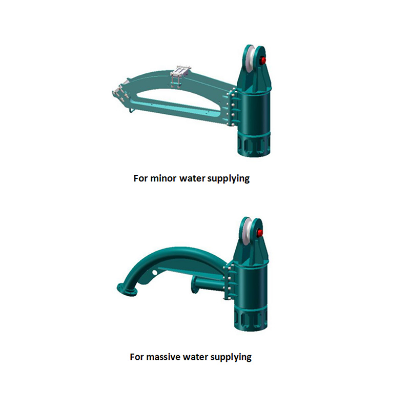
Deep soil compaction relies on heavy-duty equipment operating under extreme dynamic loads. Rigs often reach depths of up to 75 meters to densify loose soils and increase load-bearing capacity. Project engineers focus heavily on the compaction probe's motor and eccentric weight. However, the connection point—the vibroflot lifting head—is frequently overlooked until a catastrophic mechanical failure halts the project.
The lifting head is not just a suspension point. It is a complex mechanical assembly responsible for load transfer, vibration isolation, utility routing, and operational safety. This guide breaks down the engineering requirements of the lifting head. We cover how it enables the successful rearrangement of soil particles to prevent land subsidence. You will learn how to evaluate structural integrity and what criteria to use when sourcing replacement components.
The lifting head isolates high-frequency vibrations from the base crane, preventing structural fatigue in the carrier machine during intense granular soil compaction.
A properly engineered vibroflot extension tube connection ensures vertical alignment and prevents shear failure under lateral soil resistance.
Evaluating a lifting head requires strict attention to metallurgical data, dynamic load ratings, utility routing (electrical vs. hydraulic), and the quality of the integrated vibration dampers.
Partnering with a specialized vibroflot accessory supplier ensures component compatibility and reduces the risk of operational downtime.
Anatomy and Function of a Vibroflot Lifting Head
The lifting head sits at the absolute top of the vibroflot string. It serves as the mechanical interface between the base crane's hook and the vibrating probe below. Its primary purpose is to suspend the entire heavy assembly while simultaneously isolating the destructive vibratory energy generated during soil compaction. Without this component, high-frequency oscillations travel directly up the wire rope. This tears apart the crane boom, damages the sheaves, and destroys the winch mechanisms.
Load bearing mechanics dictate the design. The head must support the immense static weight of the vibrator, multiple extension tubes, and heavy water or air hoses. A standard 130kW to 180kW vibroflot setup can easily exceed 15 tons of static hanging weight. Alongside this static load, the head withstands severe dynamic forces. When the probe penetrates deep into the ground, it generates extreme vertical and horizontal resistance. The lifting head absorbs these shock loads. It keeps the string stable while allowing the probe to do its work.
The Vibroflot Hanging Head Assembly
A complete vibroflot hanging head assembly consists of several highly engineered sub-components working in unison. The lifting eye, or shackle connection, provides the primary attachment point for the crane. This eye is typically forged from high-tensile steel and sized to accept heavy-duty bow shackles. Below this sits the main steel housing, which encases the damping elements. Finally, the bottom of the assembly features a heavy-duty flange or fluted connection that mates directly with the extension tubes.
Utility routing presents a massive operational challenge. The assembly safely routes and protects the power supply lines feeding the probe. Electric vibroflots require heavy, thick cabling to deliver high voltage down the string. Hydraulic systems require thick, high-pressure hoses to circulate hydraulic fluid. The lifting head provides specific channels, strain relief clamps, and protective cowlings. These prevent critical lines from shearing or crushing under tension.
Job sites are unforgiving. Mud, bentonite slurry, and uneven ground complicate every lift. Assembling and disassembling these heavy components requires precision. Workers align heavy steel flanges while suspended in the air. A well-designed hanging head includes alignment guides and accessible bolting points to make field assembly safer and faster.
Why the Lifting Head Dictates Operational Safety and Soil Improvement Success
The success criteria for any vibroflotation rig is continuous, uninterrupted operation. The base machine must remain free from structural fatigue. The probe must deliver consistent densification to non-cohesive soils. The lifting head makes both outcomes possible. If the head fails to isolate vibrations, the crane requires constant maintenance. If the head fails to hold the string rigid, compaction quality drops.
Managing dynamic stress in varying soils requires immense mechanical resilience. As the probe sinks, it encounters different soil strata. It might punch through loose granular soils and suddenly hit a dense clay lens or a buried boulder. This sudden change in resistance sends massive torsional and axial forces shooting up the extension tubes. The lifting head absorbs this torsional twisting and vertical jolting. It prevents the string from snapping.
Mechanical reliability directly enables geotechnical outcomes. The project goal is to maintain continuous vibratory energy to rearrange soil particles. This process reduces the soil filtration coefficient and locks the grains into a dense matrix. It prevents future land subsidence. If the lifting head cracks or the dampers fail, the rig shuts down. Interrupted compaction leaves weak zones in the soil profile. This compromises the foundation of the future structure.
The risk of catastrophic failure carries severe safety and financial implications. A fractured lifting eye means a dropped probe. Dropping a 75-meter string of heavy steel into a borehole destroys the equipment. It creates a massive safety hazard for the ground crew. Even a partial failure, like a warped flange, leads to uneven soil compaction. Crews struggle to extract the bent string from the ground, causing severe project delays.
The Engineering Behind Vibroflot Vibration Damper Support
The design of the vibration damper directly impacts the longevity of the entire rig and the efficiency of the compaction process. A rigid steel-to-steel connection instantly transfers the probe's destructive energy to the carrier. By evaluating the feature-to-outcome relationship of the dampers, engineers predict how long a rig will operate before requiring major overhaul.
Protecting the base crane is the primary job of the vibroflot vibration damper support. Vibroflots typically operate at horizontal and vertical oscillations between 30 and 50 Hz. These high-frequency vibrations are perfect for liquefying sand but lethal to crane booms, wire ropes, and hydraulic winches. Heavy-duty elastomeric blocks or specialized spring dampers absorb these frequencies. They dissipate the kinetic energy as heat before it travels up the lifting line. Modern cranes rely on sensitive Load Moment Indicators (LMI) and electronic sensors. Unmitigated vibrations destroy these sensors, rendering the crane inoperable.
Evaluating damper quality requires looking closely at material science. High-end dampers utilize specialized polyurethane blends or heavily reinforced synthetic rubber. These materials maintain their elastic properties under extreme duress. Inferior damping materials degrade rapidly. Continuous cyclic loading, high ambient temperatures, and the intense resistance of densifying granular soils cause cheap rubber to harden, crack, or melt. Once the damper degrades, vibration isolation fails entirely.
Damper Material
Vibration Absorption
Durability in Harsh Conditions
Best Application
Standard Natural Rubber
Moderate
Low. Prone to cracking under high heat and UV exposure.
Light-duty, shallow compaction projects.
Reinforced Synthetic Rubber (Neoprene)
High
Good. Resists oil, grease, and moderate temperature fluctuations.
Standard deep soil compaction in temperate climates.
Specialized Polyurethane
Very High
Excellent. High tear resistance and maintains elasticity under extreme cyclic loading.
Heavy-duty, continuous offshore or deep foundation projects.
Securing the String: The Vibroflot Extension Tube Connection
The structural integrity of the entire rig relies on the joint where the lifting head meets the first extension tube. This connection point acts as the structural bottleneck for the entire assembly. It holds the static weight of the string while enduring the aggressive lateral whipping motion generated by the eccentric weight spinning at the bottom of the hole.
Industry standards generally utilize two common connection methods: bolted flanges and pinned joints. Bolted flanges offer superior joint rigidity. They lock the vibroflot extension tube connection tightly, ensuring zero play between the components. This rigidity maximizes energy transfer into the soil. Pinned connections allow for faster assembly and disassembly on the job site. However, they introduce slight movement, which accelerates wear over thousands of operating hours.
Preventing shear and thread stripping is critical during the extraction phase. Pulling a compacted probe out of newly densified ground requires immense upward pull-out force. The ground grips the probe tightly. High-tensile bolts and precise machining tolerances are mandatory. Field crews often use M30 or larger high-strength bolts tightened to specific torque values, sometimes exceeding 1500 Nm. If the bolt holes are slightly misaligned or the steel is too soft, extreme pull-out forces shear the bolts or strip the threads. This leaves the probe buried permanently in the compacted earth.
Technical Criteria for Evaluating a Lifting Head for Vibroflot Equipment
When sourcing a lifting head for vibroflot equipment, site engineers must look past basic dimensions. You need to evaluate the core engineering specifications. The materials used dictate the lifespan of the component. High-yield structural steel, such as 42CrMo4 or equivalent grades, is mandatory. The steel undergoes specific heat treatments, including quenching and tempering. This achieves the necessary tensile strength and impact toughness required to withstand deep-compaction stresses.
Power source compatibility dictates the internal geometry of the lifting head. Electric and hydraulic probes require completely different utility routing setups. Mismatching the head to the probe leads to crushed lines and immediate electrical shorts or fluid blowouts.
Feature
Electric Vibroflot Lifting Head
Hydraulic Vibroflot Lifting Head
Utility Routing
Wide channels for thick, high-voltage power cables.
Multiple ports for high-pressure fluid supply and return hoses.
Strain Relief
Rubberized clamping blocks to prevent cable jacket abrasion.
Heavy-duty steel clamps to secure hoses against pressure spikes.
Sealing Requirements
Waterproof glands to prevent moisture ingress to electrical connections.
Spill-proof quick-disconnect fittings for hydraulic fluid containment.
Clearance Needs
Large bend radii to prevent internal wire breakage.
Rigid routing to prevent hoses from kinking under pressure.
Load testing and certification provide the only verifiable proof of safety. A lifting head must come with documented proof loads. Manufacturers perform non-destructive testing (NDT), such as ultrasonic or magnetic particle inspection, on all critical load-bearing welds. Compliance with international lifting equipment standards, such as ISO, CE, or strict local equivalents, is non-negotiable for site safety compliance.
Dimensional accuracy ensures seamless integration. The new lifting head features exact machining tolerances to mate perfectly with existing OEM extension tubes and vibrators. Even a millimeter of deviation on a flange face causes uneven bolt tension. This leads to rapid fatigue failure under dynamic loading.
Implementation Risks and Maintenance Protocols
Operating heavy vibratory equipment guarantees component wear. Recognizing common wear patterns allows crews to replace parts before they fail catastrophically. The lifting eye often suffers from elongation due to the constant vertical yanking of the crane. Elastomeric dampers are prone to cracking or crumbling from heat and cyclic stress. The bottom flange suffers deformation caused by aggressive lateral shifting when the probe hits hard underground obstacles.
Implementing a routine inspection framework keeps the rig running safely. Field crews follow strict daily and weekly protocols.
Conduct a daily visual inspection of the lifting eye for any signs of stretching or micro-cracking.
Check all flange bolts daily with a calibrated torque wrench to ensure they have not vibrated loose.
Inspect the utility routing channels for any signs of cable abrasion or hydraulic fluid weeping.
Perform weekly measurements of the vibration dampers to check for compression set or material degradation.
Schedule monthly non-destructive testing (NDT) on the main housing welds using dye penetrant or ultrasonic tools.
Verify the integrity of the strain relief clamps to ensure power cables are not bearing the weight of the string.
Log all inspection data to track wear trends and predict necessary replacement intervals.
A proactive mitigation strategy focuses on the dampers. Maintaining a strict replacement schedule for the vibration dampers prevents secondary damage. When dampers wear out, they stop absorbing energy. That energy transfers directly into the steel housing, causing weld fatigue and flange warping. Replacing rubber elements on a schedule ensures uninterrupted soil stabilization and protects expensive steel components.
Sourcing Strategy: Choosing a Vibroflot Accessory Supplier
Procuring heavy geotechnical components requires vetting the manufacturer thoroughly. When assessing a vibroflot accessory supplier, look for in-house manufacturing capabilities. A supplier with their own CNC machining centers controls their dimensional tolerances. Verifiable quality control processes and metallurgical transparency separate premium manufacturers from low-tier fabricators. They provide actual material test reports for their steel.
Overall value influencing factors go far beyond the initial purchase price. Weigh the conceptual trade-offs carefully. Purchasing cheap aftermarket parts saves budget upfront, but it introduces massive risk. A shattered lifting head causes days of rig downtime, crane repair costs, and potential safety liabilities. Investing in precision-engineered components guarantees project continuity and keeps the compaction schedule on track.
After-sales and technical support are critical for deep foundation projects. A reliable supplier provides accurate technical drawings to ensure compatibility before purchase. They offer clear installation guidance for field crews. Most importantly, they maintain reliable lead times for critical spares. If a component wears out, a replacement reaches the job site immediately.
Conclusion
Compile your specific rig specifications, including probe weight, crane capacity, and maximum operating depth.
Measure your existing flange dimensions and verify your power type (electric or hydraulic) to guarantee compatibility.
Request material test reports and NDT certifications alongside the initial quote to verify structural integrity.
Establish a clear maintenance and replacement schedule for the new dampers upon installation.
FAQ
Q: What is the primary function of a vibroflot lifting head?
A: The lifting head suspends the entire vibrator string from the base crane. It isolates destructive high-frequency vibrations, preventing structural damage to the carrier machine. Additionally, it provides safe routing for electrical cables or hydraulic hoses required for deep soil compaction.
Q: How does the lifting head differ for electric vs. hydraulic vibroflots?
A: Electric lifting heads feature wide channels and rubberized strain relief for thick, high-voltage power cables. Hydraulic heads utilize multiple ports and heavy-duty steel clamps to secure high-pressure fluid supply and return hoses, preventing leaks and pressure blowouts.
Q: How often should the vibroflot hanging head assembly be inspected?
A: Crews must perform visual inspections daily to check for loose bolts, lifting eye elongation, and damper degradation. Periodic non-destructive testing (NDT), such as ultrasonic or dye penetrant inspections on critical welds, should occur monthly or after any severe operational impacts.
Q: Why is the vibroflot vibration damper support necessary?
A: The damper support absorbs the 30-50 Hz oscillations generated by the probe. Without it, resonant frequency vibrations would travel up the lifting line, causing rapid metal fatigue and catastrophic structural damage to the crane boom and winch during granular soil densification.
Q: Can I use a third-party lifting head for vibroflot equipment?
A: Yes, provided the third-party supplier guarantees exact OEM dimensional tolerances. The replacement head must match your flange connections perfectly, meet your specific load certification requirements, and be fully compatible with your probe's power type to ensure safe operation.
Q: What causes a vibroflot extension tube connection to fail?
A: Failures typically result from improper bolt torque, metal fatigue from continuous vibration, or lateral over-stressing. Extreme upward pull-out forces during probe extraction can also shear bolts or strip threads if the connection is weakened or misaligned.
Q: What information is needed for a vibroflot lifting component inquiry?
A: You must provide the total probe weight, power type (electric/hydraulic), base crane capacity, exact flange dimensions, bolt hole patterns, and the maximum operating depth to ensure the manufacturer engineers a compatible and safe lifting head.