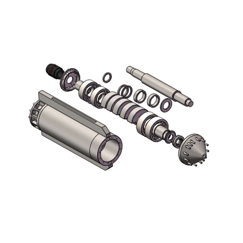
Equipment failure during deep foundation and soil stabilization projects results in compounding downtime costs, idle crew expenses, and delayed project milestones. Vibroflots operate in extremely harsh subsurface environments, enduring constant high-frequency vibration, abrasive granular soil, and high-pressure water or air exposure. Whether executing vibro compaction in loose sands or vibro replacement with crushed stone, critical components degrade rapidly without rigorous, standardized upkeep. Mitigating these risks requires moving from reactive repairs to a proactive, evidence-based maintenance protocol. This guide details the essential components of a robust vibroflot maintenance checklist to ensure equipment longevity, accurate densification, and operational reliability.
Component-Specific Protocols: Effective maintenance requires distinct inspection criteria for the motor, vibration body, dampening systems, and feed mechanisms, as each degrades under different operational stresses.
Interval-Based Execution: A rigid schedule of daily pre-operation checks, weekly technical assessments, and post-project teardowns is non-negotiable for preventing catastrophic failure.
Resource Allocation: Determining whether to execute maintenance in-house or partner with a specialized vibroflot maintenance support service depends on internal technical capacity and project scale.
Data-Driven Monitoring: Tracking penetration rates, withdrawal resistance, and operating temperatures via calibrated control panels provides early warning signs of internal mechanical wear before failure occurs.
Why a Structured Vibroflot Equipment Maintenance Checklist is Critical
Defining the baseline for successful ground improvement operations starts with equipment reliability. The primary success criteria include zero unplanned downtime, sustained compaction efficiency, accurate probe location tracking, and an extended lifecycle for high-capital components. Achieving these metrics requires strict adherence to a formalized vibroflot equipment maintenance checklist. Relying on memory or informal checks leads to inconsistent equipment performance and unexpected breakdowns on the job site.
Neglecting routine maintenance carries severe operational consequences. Moisture ingress into the motor housing causes stator winding failure, instantly halting production and requiring a massive overhaul. Degraded bearing oil leads to rapid overheating and catastrophic bearing seizure inside the vibration body. When the equipment underperforms, soil densification quality drops. This forces crews to execute costly, time-consuming rework to meet project compaction specifications. A compromised machine directly threatens the structural integrity of the foundation it prepares.
Standardization eliminates operator guesswork. A documented checklist ensures every technician evaluates the equipment against identical criteria. It enforces compliance with site safety standards and manufacturer guidelines. Strict documentation also preserves warranty validity. When component failures occur, manufacturers require comprehensive maintenance logs to process claims. Standardized protocols transform maintenance from a reactive scramble into a predictable, manageable operational phase.
Field mechanics face unique challenges when servicing heavy machinery over open excavations or on muddy platforms. A structured approach ensures they do not miss easily overlooked components like secondary O-rings or hidden grease zerks. By forcing a systematic walkaround, the checklist acts as a physical barrier against complacency. It guarantees that the machine entering the ground today is just as capable as it was on day one of the project.
Core Components of a Vibroflot Maintenance Protocol
A vibroflot is a complex assembly of mechanical, electrical, and structural subsystems. Effective maintenance breaks the equipment down into these specific categories. Each subsystem requires distinct evaluation dimensions based on its operational function and wear patterns.
Vibroflot Motor Inspection
The motor drives the eccentric weight, generating the centrifugal force required for soil compaction. A thorough vibroflot motor inspection prevents sudden power losses during deep penetration.
For electric motors, moisture is the primary threat. Technicians must check insulation resistance using a Megger tester. Applying a 500V or 1000V test helps detect moisture ingress or winding degradation before a short circuit occurs. Inspect power cable integrity daily. Focus heavily on the connection points at the vibroflot head. These areas endure extreme flexural stress and are highly susceptible to fatigue. Monitor the operating amperage during soil penetration. Establishing a baseline allows operators to detect abnormal load spikes. Sudden increases in amperage often indicate internal bearing wear or excessive friction.
Executing a proper electrical motor inspection requires specific steps:
Disconnect all power sources and lock out the main control panel.
Connect the Megger tester leads to the motor phase cables and the ground casing.
Apply the test voltage for exactly 60 seconds to obtain a stable insulation resistance reading.
Record the value in the maintenance log. Any reading below 100 Megohms requires immediate investigation for moisture.
Inspect the heavy-duty cable glands at the top of the motor housing for cracked rubber seals.
Hydraulic motors require different diagnostic approaches. Inspect all hydraulic hoses for abrasion, bulging, or external leaks. High-pressure fluid leaks pose safety hazards and reduce compaction force. Test operating pressure and flow rates using inline flow meters. Compare these readings against manufacturer specifications to ensure the hydraulic pump and motor operate efficiently. Analyze hydraulic fluid samples regularly. Look for water contamination, which appears milky, or particulate matter that accelerates internal component wear.
Vibroflot Vibration Body Maintenance
The vibration body houses the eccentric weights and heavy-duty bearings. It absorbs the most intense mechanical stress during operation. Proper vibroflot vibration body maintenance prevents catastrophic mechanical lockups.
The bearing assembly demands meticulous attention. Check bearing oil levels before every shift. Assess the oil coloration and viscosity. Dark, thick, or burnt-smelling oil indicates severe overheating. Metal shavings on the magnetic drain plug signal rapid bearing degradation. Adhere strictly to the manufacturer's oil replacement intervals, using only the specified high-temperature synthetic gear oil.
Inspect the eccentric weight system for abnormal vibration signatures. Listen for acoustic changes, such as knocking or grinding sounds, which indicate loose or damaged eccentric components. Conduct visual and non-destructive testing (NDT) on the external casing. Use dye penetrant or ultrasonic testing to identify micro-fractures and weld fatigue. Pay special attention to wear patterns on the casing. Angular crushed stone used in vibro replacement causes significantly faster abrasion than rounded gravel used in vibro compaction. Measure casing wall thickness to determine when hard-facing or replacement is necessary.
Component
Inspection Method
Warning Signs
Action Required
Main Bearings
Oil sample analysis & magnetic plug check
Burnt smell, metal flakes, milky color
Flush housing, replace oil, schedule teardown if metal is present
External Casing
Ultrasonic thickness gauge
Wall thickness drops below manufacturer minimum
Apply hard-facing weld or replace casing section
Eccentric Shaft
Acoustic monitoring & vibration analysis
Rattling, knocking, or irregular vibration frequency
Remove from service immediately for internal inspection
Vibroflot Vibration Damper Inspection
The dampening system isolates the extreme high-frequency vibrations of the probe from the carrier rig. A failing damper transfers destructive energy upward, risking severe damage to the crane or drill rig. Executing a precise vibroflot vibration damper inspection protects your heavy machinery.
Evaluate the elastomer elements closely. Look for cracking, surface hardening, or physical deformation. Continuous high-frequency isolation generates internal heat, causing rubber and synthetic dampening elements to degrade over time. Check the torque on all structural bolts and fasteners. Ensure the connections between the damper, the follower tube, the vibration body, and the mounting points on the carrier rig remain tight. Assess the overall isolation efficiency during operation. If excessive vibration transfers up the follower tubes, the damper system is failing and requires immediate replacement.
Feed Systems: Top Feed vs. Bottom Feed
Maintenance protocols must adapt to the specific feed mechanism used for introducing backfill material.
Bottom feed systems, used primarily for vibro replacement, feature complex material delivery pathways. Inspect the gravel hopper for structural integrity. Ensure the hydraulic gates open and close smoothly without binding. Clear any blockages in the delivery system. Measure the wall thickness of the tremie pipe and delivery tube. The continuous flow of crushed aggregate causes severe internal abrasion. Replace worn sections before they rupture underground.
Top feed systems, used for vibro compaction, rely on surface flushing. Ensure the annulus space around the probe remains clear of debris. Inspect the upper water jets used to flush granular soil down the probe hole. Clogged upper jets prevent proper material flow, leading to inadequate soil densification and probe entrapment.
Jetting System and Fluid Delivery
The jetting system fluidizes the soil, allowing the vibroflot to penetrate to the target depth. Inspect the bottom and side water or air jetting ports daily. Clear any blockages caused by silt, clay, or backfill material. Clogged nose cone ports force the motor to work harder, increasing operating temperatures and fuel consumption.
Evaluate the integrity of all valves, O-rings, and seals. High-pressure jetting and deep dewatering phases create massive external hydrostatic pressure. Worn seals allow abrasive slurry and water to bypass the protective casing and enter the vibration body. Replace seals proactively during scheduled teardowns to prevent internal flooding.
Control Panel and Data Logging Systems
Modern ground improvement relies heavily on data. The control panel tracks critical implementation metrics, including penetration depth, penetration rate, withdrawal rate, and amperage. Regularly calibrate all sensors to ensure data accuracy. Faulty sensors lead to incorrect compaction reporting and potential project rejection.
Inspect the control panel wiring and PLC connections. The continuous vibration from the site environment causes terminal screws to loosen. Check for moisture damage inside the panel enclosure. Ensure all digital displays function correctly and that the data logger successfully exports records to the site engineer's database.
Maintenance Intervals: Daily, Weekly, and Post-Project
Establishing a realistic timeline for maintenance tasks balances operational uptime with risk mitigation. A tiered approach ensures minor issues are caught daily, while complex diagnostics occur during scheduled downtime. Field crews must integrate these checks into their standard operating procedures without exception.
Interval
Focus Area
Specific Tasks
Daily (Pre- and Post-Shift)
Visual & Fluid Checks
Inspect power cables and hydraulic hoses for damage.
Grease all exposed joints and mechanical linkages.
Check bearing oil levels and inspect for leaks.
Verify bottom and side jet ports are clear of debris.
Confirm control panel display and sensor functionality.
Weekly (In-Depth Assessment)
Technical Diagnostics
Perform Megger testing on electric motor windings.
Check and re-torque all structural bolts and fasteners.
Inspect vibration damper elastomers for cracking or shear.
Analyze data logs for penetration or withdrawal anomalies.
Measure hydraulic flow rates and operating pressures.
Post-Project (Overhaul)
Comprehensive Rebuild
Execute a complete teardown of the vibration body.
Replace heavy-duty bearings and internal seals.
Conduct NDT on casing welds and measure wall thickness.
Inspect hopper and tremie pipe for internal abrasion.
Recalibrate all control panel sensors and update PLC firmware.
Daily checks form the first line of defense. Operators must walk around the suspended equipment before the engine starts. They look for obvious signs of distress: a puddle of gear oil under the nose cone, a frayed hydraulic line, or a missing bolt on the damper assembly. These visual cues take five minutes to identify but save days of downtime.
Weekly assessments require a dedicated mechanic. This involves shutting the rig down for a few hours to perform instrumented testing. The mechanic applies torque wrenches to structural bolts, connects the Megger tester to the electrical lines, and pulls oil samples. This interval catches the invisible degradation that visual walkarounds miss.
Post-project overhauls happen in a controlled workshop environment. The equipment is completely disassembled, cleaned, and measured against factory tolerances. Bearings are replaced regardless of their apparent condition, as their fatigue life is difficult to judge visually. This reset ensures the vibroflot is ready for the next deployment.
Evaluating In-House Maintenance vs. Outsourcing
Contractors must decide how to allocate resources for heavy equipment upkeep. The decision between maintaining an internal specialized mechanic team and utilizing external expertise depends on operational efficiency, downtime risk, and resource availability.
Partnering with a Vibroflot Equipment Manufacturer
Working directly with a vibroflot equipment manufacturer offers distinct technical advantages. Manufacturers possess proprietary diagnostic tools designed specifically for their machinery. They guarantee the use of authentic OEM parts, which ensures optimal fit and longevity. Manufacturers also provide essential firmware and hardware updates for advanced control panels.
However, this approach presents logistical challenges. Shipping heavy vibration bodies to regional service centers incurs significant lead times. Manufacturer labor rates are generally higher than local mechanics. This route is best reserved for major overhauls, preserving active warranties, and executing comprehensive post-project rebuilds where precision is paramount.
Utilizing a Vibroflot Maintenance Support Service
Engaging a specialized vibroflot maintenance support service provides flexibility. These independent teams offer on-site troubleshooting and rapid deployment for emergency repairs. They bring specialized expertise in ground improvement machinery without the overhead of full-time internal staff. They can quickly address hydraulic failures, electrical shorts, or damper replacements directly on the job site.
The primary drawback is the variable quality among vendors. Contractors must vet third-party services for specific brand familiarity and technical competence. This option is ideal for mid-project emergency support. It effectively supplements in-house teams during complex diagnostics, keeping the project moving without waiting for manufacturer availability.
Implementation Risks and Mitigation Strategies
Even with a perfect checklist, execution flaws can undermine the maintenance program. Recognizing and mitigating these risks is essential for operational stability.
The most common risk is pencil-whipping. Under intense schedule pressure, operators may falsify the maintenance checklist without actually performing the inspections. Mitigate this by implementing digital checklist software. Require technicians to upload timestamped photos of fluid levels, gauge readings, and critical components. Sync these digital logs automatically with the rig's data logger to ensure accountability and track compliance.
Using non-OEM substitute parts to cut upfront costs introduces severe mechanical risk. Generic bearings or inferior seals fail rapidly under high-frequency vibration. Mitigate this by establishing strict procurement guidelines. Document the accelerated failure rates and calculate the total downtime costs associated with substandard parts. OEM parts consistently deliver better operational value despite higher initial purchase prices.
Contamination during field maintenance destroys internal components. Opening the bearing chamber to change oil in a dusty, windy environment introduces abrasive dirt directly into the system. Mitigate this by mandating controlled environments for internal fluid changes. Use proper filtration carts when transferring hydraulic fluids. If field conditions are too severe, swap the entire vibration body and perform the fluid change in a clean workshop.
Conclusion
A rigorous, documented maintenance checklist serves as an operational safeguard that directly impacts the profitability and quality assurance of ground improvement projects. Proactive maintenance prevents catastrophic failures, ensures accurate soil densification, and extends the lifespan of expensive machinery. When evaluating maintenance strategies, prioritize protocols that address specific failure modes based on the exact soil conditions and backfill materials of the site.
Audit your current field maintenance logs immediately to identify gaps in daily and weekly inspection routines.
Transition from paper logs to a digital checklist platform that requires timestamped photo verification for critical fluid and torque checks.
Establish strict procurement rules that mandate the use of OEM bearings and seals for all vibration body rebuilds.
Set up a proactive service agreement with a certified maintenance support provider to handle emergency on-site diagnostics and Tier 3 repairs.
FAQ
Q: How often should the oil in a vibroflot vibration body be changed?
A: Bearing oil should typically be changed every 200 to 300 operating hours, depending on the manufacturer's specifications. However, if the oil appears dark, smells burnt, or contains metal shavings during daily checks, it must be replaced immediately regardless of the hour count.
Q: What are the early warning signs of vibroflot motor failure?
A: Early warning signs include sudden spikes in operating amperage, abnormal heat generation, and unusual acoustic signatures like grinding. For electric motors, a drop in insulation resistance during Megger testing indicates moisture ingress, which precedes winding failure.
Q: How do you test a vibroflot vibration damper for wear?
A: Perform visual inspections for cracking, tearing, or hardening of the elastomer elements. Operationally, monitor the vibration transfer. If excessive vibration travels up the follower tube to the carrier rig, the damper has lost its isolation efficiency and requires replacement.
Q: How does the maintenance checklist differ between top-feed and bottom-feed vibroflot systems?
A: Bottom-feed systems require extensive checks on the material delivery pathway, including hopper hydraulics and tremie pipe wall thickness due to internal abrasion. Top-feed systems focus primarily on ensuring the annulus space and upper water flushing jets remain completely clear of debris.
Q: Why is Megger testing important for vibroflot equipment?
A: Megger testing measures the insulation resistance of electric motor windings. Because vibroflots operate in wet, high-pressure environments, moisture ingress is a constant threat. Megger testing detects microscopic insulation degradation before it causes a catastrophic electrical short circuit.
Q: How does soil and backfill type affect the vibroflot maintenance schedule?
A: Abrasive materials like angular crushed stone accelerate wear on the external casing, nose cone, and internal tremie pipes. Projects using these materials require more frequent wall thickness measurements and non-destructive testing compared to projects compacting smooth, rounded gravel or loose sands.