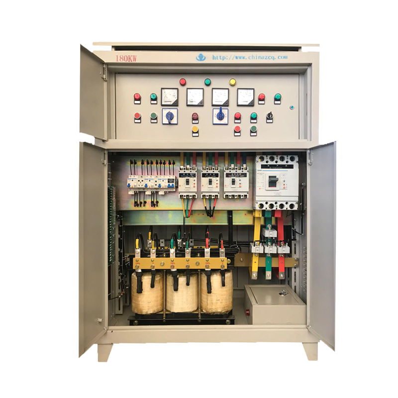
Geotechnical ground improvement projects operate in some of the most unforgiving environments on earth. When equipment fails on a compaction grid, it translates directly to severe project delays and heavy machinery standing idle. Standard industrial enclosures are entirely insufficient for vibroflotation operations. They frequently fail under the combined stress of high-amperage electrical loads, continuous mechanical vibration, and relentless exposure to mud, dust, and moisture. Selecting the correct electrical cabinet for vibroflot equipment requires a rigorous evaluation of environmental protection, power control capabilities, data integration, and site mobility. You cannot rely on off-the-shelf panels to survive these conditions. This guide provides a technical framework for specifying and sourcing a cabinet that ensures continuous, safe, and compliant site operations. We cover mechanical protection, drive sizing, and data logging requirements to keep your foundation projects moving forward without unnecessary electrical interruptions.
Key Takeaways
Environmental Resilience is Non-Negotiable: Specify minimum IP65/NEMA 4X ratings with heavy-duty vibration dampening and ruggedized mounting to protect sensitive Variable Frequency Drives (VFDs) and PLCs from site conditions.
Precision Power Control: A dedicated vibroflot frequency control cabinet must be sized not just for running current, but for the high starting torque and harmonic mitigation required by deep-compaction motors.
Data-Driven Compaction: Modern setups require seamless vibroflotation data monitor connections to log depth, amperage, and time in real-time for quality assurance and compliance reporting.
Supplier Expertise Matters: Vetting a specialized vibroflot electrical cabinet supplier ensures the integration of proper thermal management, safety interlocks, and geotechnical-specific controls.
Defining Success Criteria for Vibroflotation Enclosures
The Operating Environment
Vibroflotation sites present a uniquely hostile environment for sensitive electrical components. Enclosures must withstand high humidity, abrasive airborne dust, and extreme temperature fluctuations. You might start a shift in near-freezing conditions and end it in blistering afternoon heat. Furthermore, the continuous mechanical shock generated by the compaction process transfers directly through the ground and into nearby support equipment. A standard panel will quickly suffer from loosened terminal connections and compromised door seals under these conditions. The baseline requirement for any vibroflot electrical cabinet is the ability to isolate internal electronics from these external destructive forces. Fine silt and conductive dust are particularly damaging, as they bypass weak seals and short out exposed circuit boards.
Electrical Load Demands
Managing high-power electrically driven vibroflots requires robust power distribution architecture. Heavy-duty motors driving eccentric weights demand massive starting currents and sustained high-amperage running loads. The enclosure must accommodate oversized contactors, heavy-gauge wiring, and advanced motor protection circuits. Voltage drops over long cable runs must be calculated and mitigated. It is common for the power source to sit 50 to 100 meters away from the active probe. The internal layout must handle the thermal and electrical stress of continuous heavy-duty cycles without degrading component lifespan. If the busbars or main breakers are undersized, the resulting heat generation will cause nuisance tripping and halt production.
Regulatory & Safety Compliance
Site safety mandates and international electrical standards dictate strict compliance parameters. Enclosures must meet IEC, UL, or CE certifications depending on the operational region. Integration of mandatory safety features is non-negotiable. This includes robust lockout/tagout (LOTO) mechanisms on the main disconnects and hardwired emergency stop (E-stop) circuits. These E-stops must instantly cut power to the motor drives without relying on software logic. Proper grounding and equipotential bonding protect operators working in wet, muddy conditions. A fault in the motor winding must trip the protection circuit immediately before the outer casing of the vibroflot becomes energized.
Evaluating Environmental and Mechanical Protection
Material Selection and IP Ratings
The structural integrity of the enclosure dictates its survival on a construction site. Material selection directly impacts corrosion resistance and longevity. IP65 or IP66 ratings are the absolute baseline. This ensures the cabinet remains completely dust-tight and protected against high-pressure water jets during routine site washdowns. Thin sheet metal will warp under field abuse, compromising the door gaskets and allowing moisture ingress.
Material Type
Characteristics
Best Application Environment
Carbon Steel (Powder Coated, 2mm+)
High structural strength, susceptible to rust if the coating is scratched or dented.
Standard inland construction sites with moderate humidity and low soil salinity.
High-humidity environments, frequent washdown areas, and tropical climates.
Stainless Steel (316L)
Maximum corrosion resistance, specifically engineered to withstand chloride exposure.
Coastal reclamation projects, marine environments, and highly corrosive soils.
Vibration Isolation and Shock Resistance
Mechanical vibration is the primary cause of electrical faults in geotechnical equipment. Low-frequency ground waves travel from the compaction point directly into the generator and control skids. You must implement multiple layers of mechanical isolation.
Install heavy-duty elastomeric shock mounts between the cabinet base and the steel transport skid.
Utilize vibration-dampening standoffs for the internal mounting backplate to protect the VFDs.
Apply DIN rail mechanical end-stops to prevent relays and terminals from sliding laterally.
Mandate the use of crimped wire ferrules on all stranded wire connections to prevent fraying and pull-outs under constant shaking.
Site Mobility and Mounting Configurations
As compaction grids progress across a site, the support equipment must move with them. The enclosure requires external structural reinforcements to survive constant relocation. Heavy-duty skid-mounted crash frames protect the cabinet body from accidental impacts with heavy machinery like excavators and loaders. Certified lifting lugs welded directly to the structural frame facilitate safe and rapid crane transport. Never accept a design where lifting eyes are bolted directly through the sheet metal roof, as this will tear under the weight of the internal transformers.
Thermal Management Solutions
High-current VFDs and step-down transformers generate substantial internal heat. Without proper thermal management, drive components will derate or fail entirely. Passive cooling, utilizing heat exchangers or forced air with IP-rated filters, works well for moderate climates. However, in environments with high ambient site temperatures, active cooling via industrial air conditioning units becomes mandatory. These AC units must maintain the internal IP rating while keeping the VFD heat sinks within manufacturer-specified temperature limits. Position the AC units to avoid blowing cold air directly onto hot components, which causes localized condensation.
Specifying the Vibroflot Frequency Control Cabinet
VFD Sizing and Motor Matching
A dedicated vibroflot frequency control cabinet relies on precise motor matching. Sizing the Variable Frequency Drive (VFD) requires looking beyond the nominal kW rating of the vibroflot motor. The drive must handle the massive starting torque required to spin up the eccentric weights inside the probe from a dead stop. This necessitates specifying heavy-duty drives with substantial overload capacities. You typically need the ability to sustain 150% of the rated current for at least 60 seconds. Undersized drives will constantly trip on overcurrent faults during the initial penetration phase, especially in dense soil layers.
Power Quality and Harmonic Mitigation
VFDs introduce non-linear loads that severely distort the power supply. This is a major issue when operating off site generators rather than stable grid power. Harmonic distortion causes generator voltage regulators to behave erratically and overheats supply cables. Integrating AC line reactors or DC chokes is the first line of defense to stabilize power and protect the motor. For larger multi-probe setups running simultaneously, active harmonic filters may be required to maintain total harmonic distortion (THD) within acceptable limits. Ignoring harmonics will lead to premature generator alternator failure.
Operator Interface and Local Controls
The human-machine interface (HMI) must bridge the gap between complex drive parameters and the realities of site operation. Touchscreens alone are highly impractical for personnel wearing heavy, mud-covered PPE. The panel face requires ruggedized, IP66-rated physical pushbuttons for essential functions like start, stop, and hoist control. Clear, high-visibility visual indicators allow operators to monitor compaction progress and equipment status at a glance from a distance. Analog current meters are often preferred over digital readouts because the physical needle movement provides immediate visual feedback on soil resistance changes.
Integrating the Vibroflot Control System Cabinet
Vibroflotation Data Monitor Connection
Modern ground improvement relies heavily on empirical data. A well-designed vibroflot control system cabinet acts as the central hub for site intelligence. Establishing a reliable vibroflotation data monitor connection requires specific hardware interfaces to accept inputs from external sensors. These include depth encoders mounted on the crane winch and pressure transducers on the hydraulic lines. The system captures real-time amperage, penetration depth, and compaction time at specific intervals. This data flow generates automated QA/QC reports that verify soil bearing capacity improvements to the consulting engineers. Without this data, you cannot prove the ground has been adequately treated.
PLC and Automation Capabilities
The Programmable Logic Controller (PLC) elevates the equipment from manual operation to an automated compaction system. The PLC automates penetration and withdrawal sequences based on specific current thresholds. When the motor amperage reaches the target value, indicating the surrounding soil has achieved maximum density, the PLC signals the operator or automated winch to lift the probe to the next depth increment.
For large-scale projects, multi-probe synchronization is highly advantageous. The control system manages multiple vibroflots operating simultaneously from a single power source. This supports complex triangular or square compaction grid layouts. It ensures uniform energy delivery across the soil mass while preventing overlapping frequency interference between adjacent probes.
Telemetry and Remote Diagnostics
Downtime on a geotechnical site is exceptionally costly. Integrating cellular or radio modems into the control architecture enables remote diagnostics. This allows engineers to monitor drive performance, push firmware updates, and perform off-site data logging without deploying a technician to a remote location. When a fault occurs, remote access allows the support team to immediately identify whether the issue is a simple sensor failure or a critical drive fault. This drastically reduces troubleshooting time and ensures the correct replacement parts are dispatched to the site.
Sizing, Layout, and Implementation Realities
Calculating Enclosure Dimensions
Proper sizing prevents thermal throttling and simplifies field maintenance. Calculating the required internal volume involves more than just measuring the component footprint. Designers must account for the minimum wire bending radii of thick motor cables. You must strictly adhere to manufacturer-specified heat dissipation clearances around the VFDs and transformers. Cramping components into an undersized box restricts airflow and guarantees premature failure. Always leave at least 20% spare DIN rail space for future control relays or sensor modules.
Field Wiring and EMI Segregation
Terminating heavy-gauge, multi-core motor cables in the field is a cumbersome process. Enclosures must feature heavy-duty, removable gland plates at the base to allow electricians to drill custom entry points easily. Using brass cable glands ensures proper grounding of armored cables.
Electromagnetic interference (EMI) is a major risk when mixing high-power drives with sensitive data loggers. Implementing strict EMI best practices is mandatory. You must physically segregate high-voltage motor feeds from low-voltage sensor cables within the cabinet. Use separate wire ducts, grounded steel partitions, and shielded twisted-pair cables. This prevents electrical noise from corrupting the critical data monitor connections and causing false depth readings.
Design for Field Serviceability
When components fail, field technicians need immediate, unobstructed access. A modular component layout ensures that a failed contactor or relay can be swapped without dismantling adjacent hardware. Easily accessible terminal blocks speed up the diagnostic process. Secure clearly labeled wiring diagrams inside the door using a heavy-duty document pocket. Use standardized electrical wear parts, such as standard DIN-rail fuses and widely available contactors, to minimize downtime during emergency field maintenance. Proprietary components will leave your equipment stranded waiting for overseas shipping.
Implementation Risks and Mitigation
Deploying electrical infrastructure in outdoor environments introduces specific risks that must be engineered out during the design phase.
Internal Condensation: Rapid temperature drops at night cause moisture to condense on sensitive circuit boards. Mitigation: Install anti-condensation space heaters wired to internal thermostats to keep the ambient temperature inside the cabinet above the dew point.
Grounding Failures: Poor grounding leads to dangerous touch voltages and erratic sensor readings. Mitigation: Install dedicated heavy-copper ground busbars, ensure strict adherence to equipotential bonding standards, and verify earth resistance at every new grid location.
Dust Ingress During Maintenance: Opening the cabinet doors in high winds exposes components to dust. Mitigation: Install secondary clear acrylic dead-front panels over sensitive electronics to protect them while technicians probe terminal blocks.
How to Vet a Vibroflot Electrical Cabinet Supplier
Assessing Geotechnical Expertise
Not all panel builders are equipped to handle the demands of heavy civil construction. It is vital to differentiate between general industrial electrical panel builders and a specialized vibroflot electrical cabinet supplier. A supplier with specific experience in deep foundation and vibrocompaction equipment understands the nuances of eccentric load starting torques. They understand the necessity of severe vibration isolation and the specific data logging requirements demanded by geotechnical engineers. Ask potential suppliers for case studies of their panels operating in similar soil and climate conditions.
Customization vs. Standardization
Project timelines often force a choice between off-the-shelf industrial cabinets and custom-engineered solutions. Standardized panels offer faster lead times, but they frequently lack the structural reinforcement and specific VFD parameters required for vibroflots. Custom-engineered solutions deliver vastly higher reliability. They are optimized for the specific kW rating of your vibroflots, integrate seamlessly with your preferred data loggers, and feature mounting hardware designed specifically for your site machinery. The initial lead time is longer, but the reduction in field failures easily justifies the wait.
Structuring a Vibroflot Control Equipment Inquiry
To receive an accurate and functional proposal, your initial communication must be highly detailed. When structuring a vibroflot control equipment inquiry, include exact specifications in your Request for Quote (RFQ). Provide the exact kW rating, nominal amps, and required overload capacity of your motors. Detail the input voltage, frequency, and whether the primary source is grid power or a diesel generator. State the site ambient temperature range, humidity levels, and required IP rating. Specify the required data logging parameters and whether the unit requires a crash frame or specific skid dimensions.
Conclusion
Audit your current or planned vibroflot motor specifications to determine exact running and starting current requirements before contacting vendors.
Define your site's environmental extremes, including peak ambient temperatures and dust exposure, to establish the required IP rating and cooling methods.
Map out your data logging requirements based on the consulting engineer's quality assurance demands to ensure seamless sensor integration.
Compile this technical data to initiate a detailed supplier inquiry with a specialized geotechnical equipment manufacturer.
FAQ
Q: What IP rating is required for a vibroflot electrical cabinet?
A: A minimum rating of IP65 or NEMA 4X is required. This ensures the enclosure is completely dust-tight to protect against abrasive airborne particles. It also guarantees the cabinet can withstand low-pressure water jets from any direction, which is essential during heavy rain or routine high-pressure site washdowns.
Q: How does a vibroflot frequency control cabinet improve compaction?
A: By utilizing Variable Frequency Drives (VFDs), the cabinet allows operators to precisely control the motor speed and the resulting eccentric force. This optimizes the vibrational amplitude for different soil types, maximizes compaction efficiency, and prevents motor burnout during hard driving conditions in dense strata.
Q: What data is tracked through a vibroflotation data monitor connection?
A: The system tracks real-time motor current (amperage), penetration depth, withdrawal increments, and elapsed time. These metrics are continuously logged to generate automated reports, which are critical for verifying to engineers that the target soil bearing capacity has been achieved.
Q: Can standard industrial enclosures be used for vibroflot equipment?
A: No. Standard enclosures fail rapidly on geotechnical sites due to a lack of internal vibration isolation. They also suffer from inadequate thermal management for high-load VFDs, insufficient ingress protection against mud, and the absence of ruggedized skid mounting required for constant crane relocation.
Q: How do I prevent electrical interference between the motor drives and data monitors?
A: Preventing interference requires strict internal cabinet layout practices. You must physically segregate high-voltage motor wiring from low-voltage sensor cables using separate wire ducts, grounded steel partitions, and shielded twisted-pair cables for all data connections.
Q: What information is needed for a vibroflot control equipment inquiry?
A: You must provide exact motor specifications (kW and amps), power supply details (generator vs. grid), environmental temperature extremes, structural mounting needs (skids or crash frames), and the specific data logging integrations required for your project.