Many project managers fall into a common procurement trap. They assume buying a high-specification vibroflot probe guarantees successful soil stabilization. Standalone equipment cannot adapt to complex stratigraphy on its own. Hardware without integrated engineering support causes severe problems on site. It often leads to inadequate densification. You may face unexpected project delays. Failed load tests become a real threat when operators misunderstand the ground conditions. Soil mechanics are highly variable. A probe that works perfectly in clean sand will fail in silty clay if the methodology is wrong. Mitigating subsurface risk requires a fundamental shift in strategy. You must move away from buying a single piece of machinery. Instead, you need to invest in a complete vibroflotation solution. This holistic approach includes precise design, thorough commissioning, and expert site execution. It ensures the equipment actually performs in your specific soil conditions. We see too many contractors fail because they treat geotechnical engineering like a simple equipment purchase.
- Procuring a vibroflot is only a fraction of the investment; project success relies heavily on site-specific engineering and execution methodology.
- A true vibroflotation solution integrates equipment selection with precise geotechnical design to address granular soil variables, accelerate soil drainage, and reduce inequable settlement risks.
- Partnering with a comprehensive ground improvement equipment supplier reduces downtime through expert installation, commissioning, and operator training.
The Gap Between Hardware Procurement and a Ground Improvement Solution
Defining project success requires looking beyond the machinery. The ultimate deliverable is never just an operational vibroflot. The goal is verifiable soil bearing capacity. You need accelerated soil drainage. Long-term consolidation is absolutely necessary for structural integrity. A spinning motor does not guarantee dense soil. The equipment must interact correctly with the ground. Operators must understand how to manipulate the probe. They need to read the soil's real-time feedback. Only then can you achieve your engineering targets.
A hardware-only approach has severe limitations. Purchasing equipment in a vacuum ignores critical site variables. You must consider the fines content in the soil. Groundwater levels drastically change compaction dynamics. The target depth of improvement dictates equipment sizing. Environmental constraints often limit water usage or noise. A standard probe might work perfectly in clean sand. It will fail miserably in silty soils without proper methodology. You cannot force a generic machine to solve specific geotechnical problems.
Fragmented workflows carry heavy financial and scheduling risks. Separating equipment procurement from geotechnical engineering is dangerous. It creates a disconnect between theory and practice. The design engineer might specify a certain compaction radius. The purchased equipment might lack the amplitude to achieve it. This forces crews to drill more points. Drilling more points wastes time and fuel. Integrating these steps into a unified ground improvement solution prevents these costly mismatches.
Here are the primary failures associated with a hardware-only procurement strategy:
- Ignoring the specific fines content of the soil, leading to ineffective vibration transfer.
- Failing to account for high groundwater tables that alter the required flushing pressure.
- Underestimating the target depth, resulting in equipment that cannot reach the necessary bearing strata.
- Overlooking environmental restrictions regarding noise and spoil generation on urban sites.
- Assuming a single probe configuration will work across varying soil profiles on the same site.
Anatomy of an End-to-End Vibroflotation Solution
Phase 1: Site-Specific Vibroflotation Design
Pre-project engineering is an absolute necessity. You cannot guess grid spacing or target depths. Initial soil reports drive these critical decisions. Standard Penetration Test (SPT) data reveals the current soil density. Cone Penetration Test (CPT) data highlights weak layers. Engineers use this data to calculate the required compaction criteria. They determine if a triangular or square grid works best. They calculate the exact distance between compaction points. This prevents overlapping zones and wasted effort.
The design phase dictates the entire methodology. Clean, granular soils respond well to deep vibro compaction. The vibrations collapse the loose soil structure. The sand grains rearrange into a denser state. Mixed or cohesive soils require a different approach. They do not densify from vibration alone. You must use vibro replacement to build stone columns. These columns reinforce the weak soil. They also act as vertical drains to accelerate consolidation. Proper vibroflotation design ensures you choose the correct method before mobilizing equipment.
Engineers must evaluate several soil parameters during this phase:
- Particle size distribution to determine the suitability of pure vibration.
- Undrained shear strength to assess the risk of borehole collapse.
- Permeability coefficients to calculate the required drainage acceleration.
- Pre-consolidation pressure to understand the soil's stress history.
Phase 2: Strategic Vibroflot Equipment Selection
Matching equipment to the design requires careful evaluation. You must analyze several technical dimensions. Frequency determines how fast the eccentric weight spins. Amplitude dictates the horizontal displacement of the probe. Eccentric force is the actual compaction energy delivered to the soil. You must also evaluate the power source. Electrical probes are common and highly efficient. Hydraulic probes offer variable frequency control. Your choice depends on site power availability and depth requirements. Proper vibroflot equipment selection prevents underpowered compaction.
The internal mechanics of the probe matter immensely. The eccentric weight mechanism inside the probe generates the necessary centrifugal force. A 30Hz frequency works well for displacing large stone in cohesive soils. A 50Hz frequency is often better for rapidly densifying clean sands. You must match these mechanical outputs to the specific soil profile.
Application scenarios dictate the feed method. You must choose between Top Feed and Bottom Feed vibroflots. Soil stability drives this choice. Borehole collapse risks demand specific equipment.
Comparison of Feed Methods
| Operational Feature | Top Feed Configuration | Bottom Feed Configuration |
| Primary Soil Condition | Stable, clean granular soils | Unstable, cohesive, or mixed soils |
| Borehole Stability Requirement | Requires the borehole to remain open naturally | Prevents collapse using an integrated tremie pipe |
| Stone Material Delivery | Stone dropped manually from the surface | Stone fed directly to the probe tip via hopper |
| Environmental Impact Profile | High water usage, significant spoil generation | Dry process, minimal spoil, cleaner site footprint |
| Maximum Depth Capability | Generally limited to shallower depths | Can reach considerable depths safely and efficiently |
Depth capabilities require specific hardware configurations. Reaching considerable depths safely is challenging. You must evaluate the necessary extension tubes. These tubes carry the water and power lines. Vibration dampeners isolate the carrier machine from the intense vibrations. You must also specify the carrier machine correctly. Cranes offer excellent depth reach and flexibility. Excavators provide rigid control for shallower applications. The carrier must handle the dynamic forces safely.
Phase 3: Vibroflot Installation Commissioning
Technical integration is a complex process. You must connect the vibroflot to the base machine. Power packs require careful calibration. Water and air supply systems must deliver consistent pressure. The water jetting system at the tip and sides of the probe must be clear of debris. Hoses and cables must be secured against abrasion. The control panel needs proper weatherproofing. Every connection point is a potential failure zone. You must verify all mechanical and electrical linkages. This ensures the system operates as a single, cohesive unit.
Factory-to-site commissioning is non-negotiable. You cannot simply plug in the machine and start drilling. Technicians must verify system calibration on site. They check hydraulic pressure integrity under load. They test high-voltage electrical safety systems. Insulation resistance is measured to prevent short circuits. The data logger receives its initial calibration. Thorough vibroflot installation commissioning prevents catastrophic equipment failures during the first week of operation.
The commissioning checklist must include:
- Verifying the structural integrity of all extension tube flange connections.
- Testing the emergency stop functions on the main control panel.
- Calibrating the flow meters for the water and air flushing systems.
- Checking the vibration dampener elastomers for proper stiffness.
- Confirming the data logger accurately records depth and amperage inputs.
Phase 4: On-Site Vibroflotation Construction Guidance
Expert supervision is vital during the initial test columns. These first few points dictate the entire project rhythm. Supervisors calibrate the target amperage for the specific soil. They determine the optimal penetration rates. They establish the exact extraction steps. If the probe drops too fast, it might deviate. If it extracts too quickly, the soil remains loose. Field experts adjust these parameters based on real-time feedback. This sets the baseline for the production columns.
Compaction hold times are a critical mechanical process. The vibroflot cannot just move up and down. It must remain at the desired depth. It stays there until the material reaches adequate density. We measure this density through specific amperage resistance spikes. As the soil densifies, it grips the probe. The motor works harder to maintain its spin. The electrical current spikes accordingly. The operator holds the position until hitting the target amperage. Amperage spikes in gravel will look different than spikes in fine sand. Operators must know how to interpret these variations.
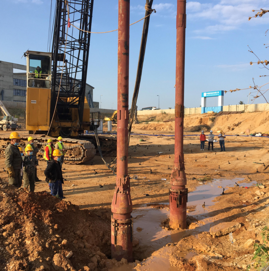
Real-time construction guidance bridges theory and practice. The design engineer provides a theoretical framework. The field supervisor makes it work in the dirt. They adjust water pressure to clear stubborn clay lenses. They modify the stone feed rate to prevent blockages in the tremie pipe. This adaptive vibroflotation construction guidance ensures verifiable soil densification. It guarantees the final load tests will pass without issue.
Evaluating a Ground Improvement Equipment Supplier
Engineering Support vs. Pure Manufacturing
You must assess whether a vendor is a true technical partner. Some companies simply weld steel and ship hardware. They offer no geotechnical insight. A credible partner analyzes your soil reports. They recommend specific methodology adjustments based on experience. They understand how their machine interacts with different stratigraphies. They do not just sell a probe. They sell a predictable engineering outcome. This distinction matters for complex projects.
A reliable ground improvement equipment supplier provides comprehensive documentation. They supply detailed method statements for your specific site. They offer strict maintenance schedules to prevent breakdowns. Performance curves show exactly how the motor behaves under load. Depth-capacity charts prove the equipment can reach your target safely. If a vendor cannot provide these documents, they are just a manufacturer. You need an engineering partner.
Look for suppliers who provide the following technical documents:
- Site-specific method statements detailing penetration and extraction protocols.
- Comprehensive maintenance schedules for daily, weekly, and monthly checks.
- Motor performance curves mapping amperage draw against soil resistance.
- Certified depth-capacity charts for various carrier machine configurations.
Quality Control and Data Logging Integration
Integrated data acquisition systems are mandatory today. You cannot rely on an operator's intuition anymore. The supplier must provide robust data logging technology. The system must record every second of the operation. It tracks the exact depth of the probe. It monitors the amperage draw continuously. It records the time spent at each depth interval. This data is stored securely for later analysis.
Real-time monitoring proves adequate density to stakeholders. Project inspectors demand verifiable proof of compaction. The data logger provides a visual graph of the process. You can see the amperage spike at every compaction step. This validates the science behind the vibroflotation process. It removes all guesswork from the quality control phase. If a column fails a later CPT test, the log reveals why. Good data logging protects both the contractor and the client.
Implementation Risks and Mitigation Strategies
Managing Inequable Settlement and Soil Variables
Encountering unexpected soil layers is a major risk. Geotechnical reports only show data from specific boreholes. The soil between those boreholes can vary wildly. You might hit unexpected cohesive soil layers. High fines content resists standard vibro compaction. The vibration simply turns wet silt into a liquid slurry. The soil will not densify properly. This leads to severe inequable settlement under the final structure.
Adaptive construction guidance is your best mitigation strategy. You must be ready to switch methodologies quickly. If the amperage does not rise, the soil is not densifying. The supervisor must recognize this immediately. They can introduce stone backfill to create a vibro replacement column. This reinforces the weak zone without halting the project. Flexibility in the field saves weeks of delay.
Equipment Mismatch and Depth Limitations
Discovering an equipment mismatch on site is a nightmare. The selected carrier machine might be too small. It cannot safely handle the combined weight of the system. The dynamic forces of the vibroflot add immense stress. Extension tubes act as a massive lever arm. A crane with insufficient capacity could tip over. An excavator might suffer severe hydraulic failure. These mismatches cause immediate, dangerous shutdowns.
Thorough carrier-matching analysis prevents this risk. The supplier must conduct this analysis during the selection phase. They calculate the total suspended load. They factor in the dynamic vibration forces. They review the crane's specific load charts. They ensure the vibration dampener is sized correctly. This guarantees the carrier can handle the required depth safely. Never guess on carrier capacity.
Operator Competency and Equipment Wear
Accelerated equipment wear is a hidden project killer. Improper penetration techniques destroy probes quickly. Forcing the probe into hard ground burns out motors. Inadequate water flushing causes the probe to overheat. Ignoring amperage limits shreds internal bearings. Operators who lack experience treat the vibroflot like a pile driver. This leads to massive repair bills and extended downtime.
Comprehensive on-site training mitigates this risk entirely. The commissioning phase must include mandatory operator instruction. Trainers establish standard operating procedures. They teach operators how to read the amperage gauges. They enforce strict hold-time protocols. Operators learn to let the water jets do the cutting. They learn specific maintenance checks, like greasing bearings and checking seal integrity. Proper training extends the life of the equipment dramatically. It also ensures consistent compaction quality across the site.
Conclusion
- Audit your current procurement strategy to ensure it includes comprehensive engineering support rather than just hardware purchasing.
- Gather and analyze all site investigation reports, including SPT and CPT data, before requesting equipment quotes.
- Request a detailed project evaluation and carrier-matching analysis from a qualified supplier to verify equipment compatibility.
- Mandate real-time data logging and on-site operator training for your next project to guarantee verifiable compaction results.
FAQ
Q: What is included in a complete vibroflotation solution?
A: A complete solution moves beyond just the probe. It includes site-specific geotechnical design and strategic equipment selection. It requires factory-to-site installation commissioning. Finally, it demands on-site construction guidance. This integrated approach ensures the equipment adapts to actual soil conditions, delivering verifiable soil bearing capacity and long-term consolidation.
Q: How do I choose the right ground improvement equipment supplier?
A: Focus on their engineering capabilities, not just manufacturing. Evaluate their ability to provide integrated data logging technology. Check their expertise in carrier-matching analysis to ensure safe operations. A strong supplier acts as a technical partner, offering post-sale site support, method statements, and real-time troubleshooting.
Q: Why is vibroflotation design critical before purchasing equipment?
A: Soil type, required bearing capacity, and target depth dictate equipment specifications. The design phase determines if you need deep compaction or vibro replacement. This dictates the specific frequency, amplitude, power source, and feed method required. Buying equipment before design often results in underpowered or mismatched machinery.
Q: What is the difference between top feed and bottom feed vibroflots?
A: Top feed is typically used for stable boreholes and loose granular soils, where stone is added from the surface. Bottom feed is designed for unstable, cohesive, or mixed soils. It uses a tremie pipe to deliver stone directly to the probe tip, preventing borehole collapse and accelerating drainage.
Q: How is soil density measured during the vibroflotation process?
A: The probe remains at specific depth intervals during extraction. It stays there until adequate density is achieved. This is measured in real-time by monitoring the electrical current (amperage) or hydraulic pressure resistance of the vibroflot motor. As soil densifies, resistance increases, causing a verifiable amperage spike.
Q: What happens during vibroflot installation commissioning?
A: Technicians assemble the entire system and integrate it with the carrier machine. They test power cables and fluid lines under load. They verify all high-voltage safety protocols and check hydraulic pressure integrity. Finally, they calibrate the data logger to ensure accurate real-time monitoring before drilling begins.
Q: How does vibroflotation construction guidance prevent project delays?
A: Expert on-site supervision helps operators interpret real-time soil feedback. When unexpected soil conditions arise, supervisors adjust penetration rates, hold times, and compaction criteria immediately. This adaptive approach prevents equipment damage and ensures the soil reaches target density without requiring costly rework or project shutdowns.


