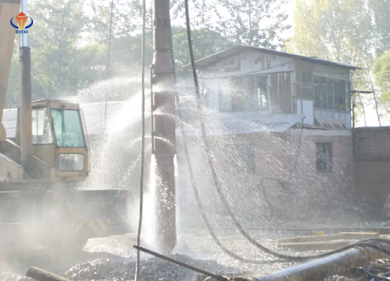
The success of vibro replacement depends entirely on matching the mechanical output of the compaction probe to the specific geotechnical realities of the site. Deploying the wrong equipment configuration directly jeopardizes foundation stability. Mismatched probes lead to inadequate bearing capacity, failure to mitigate liquefaction in seismic zones, excessive tool wear, and severe schedule delays. When the compaction energy fails to displace the surrounding soil adequately, the resulting structural integrity of the supported foundation is compromised. Specifying the correct vibroflot for stone columns requires a rigorous technical evaluation. Project managers and geotechnical engineers must navigate a complex matrix of soil properties, required column dimensions, feed methods, and operational constraints. We evaluate equipment specifications to ensure the chosen machinery aligns perfectly with site stratigraphy and project demands.
Soil shear strength, fines content, and groundwater levels are the primary dictates for choosing between top-feed and bottom-feed vibro replacement methods.
Achieving the target stone column diameter requires precise alignment of the vibroflot’s amplitude, eccentric force, and operating frequency with the surrounding soil mechanics.
Effective vibroflotation equipment selection extends beyond raw power; it requires evaluating data acquisition capabilities, rig compatibility, aggregate sizing, and supplier support infrastructure.
The Mechanics of Vibro Replacement: Defining Success Criteria
A vibroflot penetrates the ground using high-frequency vibration, downward crowd force, and fluid or air jetting. Inside the heavy tubular casing, an eccentric weight driven by an electric or hydraulic motor rotates at high speeds. This rotation generates horizontal vibrations. As the probe descends, these vibrations temporarily liquefy the surrounding granular soil or shear through cohesive layers. A heavy-duty vibration isolator sits at the top of the assembly, protecting the crane line or rig mast from absorbing these destructive dynamic forces.
You establish the criteria for a successful installation by monitoring several field metrics. The primary objective is achieving the target relative density in the matrix soil between the columns. Operators must maintain continuous vertical columns of compacted gravel without necking or soil contamination. Reaching the required depth without deviation ensures the load transfers correctly to the competent bearing strata below. The crew monitors the amperage gauge in the cab to verify the probe is working against the soil resistance rather than spinning freely in a void.
The physical specifications of the stone column construction equipment directly dictate the speed of penetration and the radial displacement of the backfill material. A probe with insufficient amplitude fails to push the crushed stone outward into the surrounding soil matrix. This results in a narrow, weak column. Optimal compaction energy maximizes the lateral displacement of the aggregate. You get a dense, wide column that interlocks firmly with the native soil.
Selecting a vibroflot with optimal compaction energy allows for wider grid spacing. When each column exerts a larger zone of influence, engineers increase the distance between installation points. This grid pattern optimization directly reduces the total number of columns required across the site footprint. Fewer columns translate to less aggregate consumption, reduced equipment wear, and accelerated project schedules. Field crews spend less time repositioning the rig and more time actively compacting stone.
Top Feed vs. Bottom Feed Vibroflot: Matching Method to Site Realities
Choosing the correct material delivery method is the first major decision in equipment specification. You base this choice on borehole stability and job site environmental constraints. The feed method dictates the entire support infrastructure required on site, from water pumps to air compressors.
Wet Top-Feed Vibroflots
The wet top-feed method relies on high-pressure water jetting from the tip of the probe. This facilitates penetration and flushes loose material to the surface. The jetting creates an annular space around the vibroflot. Once the probe reaches the design depth, operators reduce the water pressure and introduce crushed stone at the ground surface. The aggregate falls through the annular space to the tip of the probe. The operator then lifts and repenetrates the stone in lifting increments, compacting the material outward into the soil walls.
A top feed vibroflot works well for specific soil profiles, particularly loose granular soils and sites with high water tables. The hydrostatic pressure from the jetting water prevents the borehole from collapsing. The stone reaches the bottom unimpeded. It remains a highly efficient method for clean sands and gravels where fines content is minimal. The equipment setup is generally simpler, requiring only a standard crawler crane, a water pump capable of delivering sufficient flow and pressure, and a front-end loader to manage the stone at the surface.
Managing water supply and wet spoil returns presents major logistical challenges. The process generates large volumes of slurry that you must contain, settle, and dispose of properly. Crews must construct settling ponds or deploy mechanical separation plants to manage the runoff. On restricted urban sites, managing this volume of water is often unfeasible. Environmental regulations regarding sediment discharge frequently disqualify the wet method entirely.
Dry Bottom-Feed Vibroflots
The dry bottom-feed method eliminates water jetting and slurry management. This system utilizes a tremie pipe attached externally or integrated internally alongside the vibroflot casing. Compressed air pushes the crushed stone from a hopper at the surface, down the tremie pipe, and directly to the tip of the probe. The stone exits the pipe at the bottom of the hole, and the probe compacts it in upward increments. The air pressure keeps the groundwater out of the tremie pipe and assists in pushing the stone out of the discharge door.
Deploying a bottom feed vibroflot is an absolute necessity in cohesive soils, soils with high fines content, or highly stratified soils. An open borehole collapses immediately upon withdrawal of the probe in these conditions. Fines mix with the descending stone in a top-feed scenario, contaminating the column and reducing its friction angle. The bottom-feed method ensures the aggregate reaches the compaction zone cleanly. The continuous delivery of stone directly to the tip guarantees the integrity of the column from the bottom up.
Aggregate compatibility is a strict operational factor. The internal diameter of the tremie pipe must match the specified crushed gravel or stone size. Using aggregate that is too large for the pipe diameter guarantees frequent jamming. This halts production and requires the crew to extract and clear the entire assembly. Engineers specify the aggregate gradation carefully to ensure continuous material flow through the pneumatic system. The stone must be clean and free of clay lumps that could stick to the internal walls of the pipe.
These setups require specialized base machines, such as heavy-duty crawler cranes or custom piling rigs equipped with leader masts. Managing the material skip that feeds the hopper and maintaining consistent air pressure systems demands highly skilled operators. The air compressor must deliver sufficient cubic feet per minute (CFM) to keep the stone moving without blowing out the surrounding soil matrix.
Core Technical Specifications in Vibroflotation Equipment Selection
Proper vibroflotation equipment selection requires analyzing the internal mechanics of the probe. The physical output of the machine must overcome the resistance of the native soil while remaining compatible with the carrier rig.
Technical Specifications Impact Summary
Technical Parameter
Measurement Unit
Primary Impact on Construction
Operational Consideration
Centrifugal Force
kilonewtons (kN)
Penetration capability through dense layers.
Must be balanced with rig stability to prevent excessive mast vibration.
Peak-to-Peak Amplitude
millimeters (mm)
Determines the radial displacement of the stone.
Higher amplitude creates wider columns in softer cohesive soils.
Operating Frequency
Hertz (Hz) or RPM
Matches soil resonance for optimal liquefaction.
Typically set between 30 Hz and 50 Hz depending on soil gradation.
Motor Power
Kilowatts (kW)
Maintains eccentric rotation under heavy soil resistance.
Requires adequately sized generators or hydraulic power packs.
Motor Power and Eccentric Force
Centrifugal force, measured in kilonewtons (kN), determines the probe's ability to overcome soil resistance during both penetration and compaction. Inside the vibroflot, the spinning eccentric mass generates this force. Higher centrifugal force allows the probe to punch through stiff clay lenses or dense sand layers that refuse a lighter machine. It provides the brute strength needed to ram the crushed stone outward against the confining pressure of the deep soil matrix. Electric motors provide consistent RPM under load, while hydraulic motors offer variable frequency control.
Specifying equipment involves trade-offs. High-power units offer faster penetration in dense layers. However, over-sizing the equipment for lighter carrier rigs leads to severe operational instability. A massive vibroflot swinging from an undersized crane induces dangerous dynamic loads on the boom. The power output must align with the safe working load and dynamic stability limits of the base machine. You must also size the surface generator or hydraulic power pack to handle the peak starting current or pressure required by the heavy eccentric weight.
Amplitude, Frequency, and Stone Column Diameter
The peak-to-peak amplitude of the vibroflot is the most critical factor in determining the final geometry of the installation. Amplitude refers to the total lateral distance the tip of the probe travels during one full rotation of the eccentric weight. High amplitude generates massive lateral displacement, pushing the stone backfill deep into the surrounding soil walls. The bearings supporting the eccentric shaft must withstand these extreme lateral forces continuously.
Design alignment requires calculating or estimating the achievable stone column diameter based on the equipment's amplitude and the undrained shear strength of the surrounding soil. In soft, cohesive soils with low shear strength, a high-amplitude probe creates a significantly wider column. If the amplitude is too low for the soil conditions, the column remains narrow, failing to meet the area replacement ratio required by the foundation design. Field crews verify this by tracking the volume of stone consumed per vertical meter of column.
Frequency matching is equally important. Operating frequencies typically range from 30 to 50 Hz. The goal is to align the vibration frequency with the natural resonance of the target soil. Granular soils generally respond best to higher frequencies, which rapidly break the inter-particle friction and induce localized liquefaction. Cohesive soils often require slightly lower frequencies combined with higher amplitude to physically remold and displace the clay matrix without simply shearing a clean hole.
Probe Dimensions and Depth Capabilities
The physical dimensions of the vibroflot—specifically its length, weight, and extension tube compatibility—dictate its depth capabilities. Deep foundation projects often require treating soils 20 to 30 meters below grade. The standard probe connects seamlessly to heavy-duty extension tubes that transfer the power cables or hydraulic hoses safely to the surface. These connections must be watertight and capable of withstanding the continuous vibration without loosening.
Rig compatibility remains a strict limiting factor. Engineers calculate the total suspended weight, which includes the vibroflot, all extension tubes, the vibration isolator, and the bottom-feed apparatus. This combined weight must fall well within the safe working load of the carrier crane or rig at the required operating radius. Exceeding these limits risks catastrophic equipment failure and severe safety hazards on site. The rig must also have sufficient mast height or boom length to lift the entire assembly clear of the ground to initiate the next column.
Site-Specific Variables Dictating Equipment Needs
Geotechnical reports serve as the primary input for equipment specification. The data extracted from soil borings dictates exactly what mechanical forces are required to treat the ground effectively.
Soil Properties and Stratigraphy
Specific soil parameters dictate the required penetration force and feed method. Engineers analyze Cone Penetration Test (CPT) and Standard Penetration Test (SPT) data to map the soil profile. When fines content exceeds 15 to 20 percent, the soil's permeability drops. It resists the localized liquefaction required for top-feed methods. In these profiles, dry bottom-feed equipment becomes mandatory. The undrained shear strength of cohesive layers dictates the required amplitude to achieve the necessary column diameter. High CPT tip resistance values indicate dense layers that require maximum centrifugal force to penetrate.
Navigating hard lenses requires specialized equipment configurations. When penetrating stiff clay or dense sand lenses to reach the target treatment depth, standard probes face refusal. Overcoming this requires equipment capable of handling increased downward crowd force applied by a leader mast rig. The mast pushes the probe through the dense layer while the vibration breaks the friction. In extreme cases, pre-drilling compatibility is required. An auger loosens the dense layer before the vibroflot is introduced, ensuring the probe reaches the design depth without burning out the motor.
Liquefaction mitigation in seismic zones demands strict adherence to relative density targets. Equipment requirements for densifying potentially liquefiable soils focus heavily on sustained compaction energy. The vibroflot delivers consistent centrifugal force across specific grid patterns to ensure the matrix soil between the columns achieves the minimum required relative density. This prevents pore water pressure buildup during seismic events. The equipment must run continuously at peak load without overheating.
Environmental and Site Constraints
Beyond soil mechanics, above-ground realities frequently dictate equipment selection. Urban environments impose strict noise restrictions and vibration limits to protect adjacent structures. These constraints force the selection of dry bottom-feed systems over wet methods, regardless of the underlying soil type. Bottom feed systems operate much quieter than the massive water pumps required for top feed operations.
Strict spoil disposal regulations further complicate wet top-feed operations. Pumping, storing, and trucking liquid slurry off-site is heavily regulated and logistically complex in congested areas. Bottom-feed systems generate virtually no spoil. They are the only viable option for sites with zero-discharge requirements or limited footprint for settling ponds. The dry method keeps the site clean and allows follow-on trades to access the area immediately after column installation.
Evaluating a Ground Improvement Equipment Supplier
Procuring the machinery is only the first phase. The operational success of the project relies heavily on the infrastructure supporting the equipment in the field.
Technical Support and Commissioning
Partnering with a reliable ground improvement equipment supplier mitigates immense operational risk. On-site commissioning is a strict requirement. Factory technicians assemble the probe, calibrate the monitoring systems, and conduct the initial penetration tests. This ensures the equipment interacts correctly with the specific site soils. Comprehensive operator training provided by the supplier ensures the crew understands optimal lifting increments and amperage thresholds. Operators learn how to read the soil response through the behavior of the machine.
Downtime destroys project schedules. Evaluating fleet and spare parts availability is a primary concern. A supplier maintains localized inventories of high-wear items. Eccentric bearings, elastomeric isolators, and wear plates endure extreme stress and require periodic replacement. Rapid deployment capabilities for these parts prevent a minor mechanical issue from halting site production for weeks. The supplier must provide clear maintenance schedules and torque specifications for all critical bolts.
The highly abrasive nature of compacted gravel and crushed stone severely degrades equipment. Specialized wear-resistant steel, such as Hardox, is utilized on the vibroflot tip, the lower casing, and the internal surfaces of the tremie pipe. Evaluating the abrasion resistance and maintenance intervals of the equipment ensures the probe survives the duration of the project without requiring complete casing rebuilds. Field crews monitor the wear plates daily and build them back up with hard-facing welding rods as needed.
Data Acquisition and Quality Control
Modern geotechnical engineering demands verifiable proof of installation quality. Integrated rig monitoring systems are a mandatory requirement for contemporary equipment. These data loggers record depth, amperage build-up, and stone consumption in real-time. As the probe compacts the stone, the resistance increases, causing a spike in the motor's amperage. This amperage spike is the primary indicator that the stone is fully compacted against the surrounding soil. The operator holds the probe at that depth until the target amperage is reached.
Automated data logging provides compliance documentation. Engineers of record require this verifiable proof to confirm that every single stone column meets the design specifications. The data acquisition system generates a profile for each column, proving the required depth was reached, the correct volume of stone was consumed, and the target compaction energy was applied at every depth interval. This eliminates the guesswork and manual logging errors associated with older equipment.
Conclusion
Choosing a vibroflot for stone columns is a strict engineering decision balancing soil mechanics, required column geometry, and site logistics. Raw power alone does not guarantee success. The equipment delivers the correct frequency and amplitude to manipulate the specific soil profile effectively while adhering to strict environmental constraints. The shortlisting logic follows a clear decision path. First, analyze the CPT/SPT data and fines content to choose the appropriate feed method. Second, determine the required column diameter and area replacement ratio to select the necessary amplitude and centrifugal force. Finally, assess site constraints, carrier rig capacities, and spoil management rules to finalize the complete rig configuration.
Execute the following steps to finalize your equipment specification:
Extract the fines content percentages and groundwater elevations from the geotechnical report to mandate either a top-feed or bottom-feed system.
Calculate the maximum safe working load of your available carrier cranes to establish a hard limit on the total suspended weight of the vibroflot assembly.
Verify the exact gradation of the locally sourced crushed stone to ensure it falls within the acceptable tolerance of the selected tremie pipe diameter.
Submit the compiled soil boring logs and site constraint data to a specialized equipment manufacturer for a formal technical consultation and rig matching assessment.
FAQ
Q: What is the difference between a top feed and bottom feed vibroflot?
A: A top feed vibroflot uses water jetting to keep the borehole open, allowing stone dropped from the surface to fall to the tip. A bottom feed vibroflot uses an attached tremie pipe and compressed air to deliver stone directly to the tip. You use bottom feed systems in cohesive soils or environments where wet spoil is prohibited.
Q: How does vibroflot amplitude affect stone column diameter?
A: Amplitude determines the lateral distance the probe travels during vibration. Higher amplitude generates greater radial displacement, pushing the crushed stone further into the surrounding soil. This creates a wider stone column diameter. You need high amplitude in softer, cohesive soils to achieve the required bearing capacity and area replacement ratio.
Q: What soil types are suitable for vibro replacement stone columns?
A: Vibro replacement is highly effective in a wide range of soils, including loose sands, gravels, silts, and soft to firm clays. Clean granular soils are treated with top-feed methods. Soils with high fines content, like silts and clays, require bottom-feed methods to prevent hole collapse and ensure column integrity.
Q: How do you determine the required eccentric force for a vibroflot?
A: You determine the required eccentric force by analyzing the soil's density and shear strength from CPT and SPT data. Higher force is required to penetrate dense sand layers or stiff clay lenses. It also provides the energy needed to adequately compact the stone backfill against the high confining pressures of deep native soils.
Q: How does vibroflot selection impact stone column grid spacing?
A: A vibroflot with optimal compaction energy and amplitude creates wider, denser columns that exert a larger zone of influence. This allows engineers to design wider grid spacing between columns. Wider spacing reduces the total number of columns required, saves aggregate material, and accelerates the overall construction schedule.
Q: What size gravel is compatible with a bottom feed vibroflot?
A: The gravel size must be strictly compatible with the internal diameter of the tremie pipe to prevent jamming. Crews typically use crushed stone or gravel graded between 12mm and 40mm. The maximum particle size should never exceed one-third of the tremie pipe's internal diameter to ensure smooth pneumatic delivery.
Q: What data should be monitored during stone column construction?
A: Quality control requires real-time monitoring of the probe's depth, the motor's amperage or hydraulic pressure, and the volume of stone consumed per depth interval. Amperage spikes indicate compaction resistance. This automated data logging proves the column was constructed to design specifications and achieved the required density.