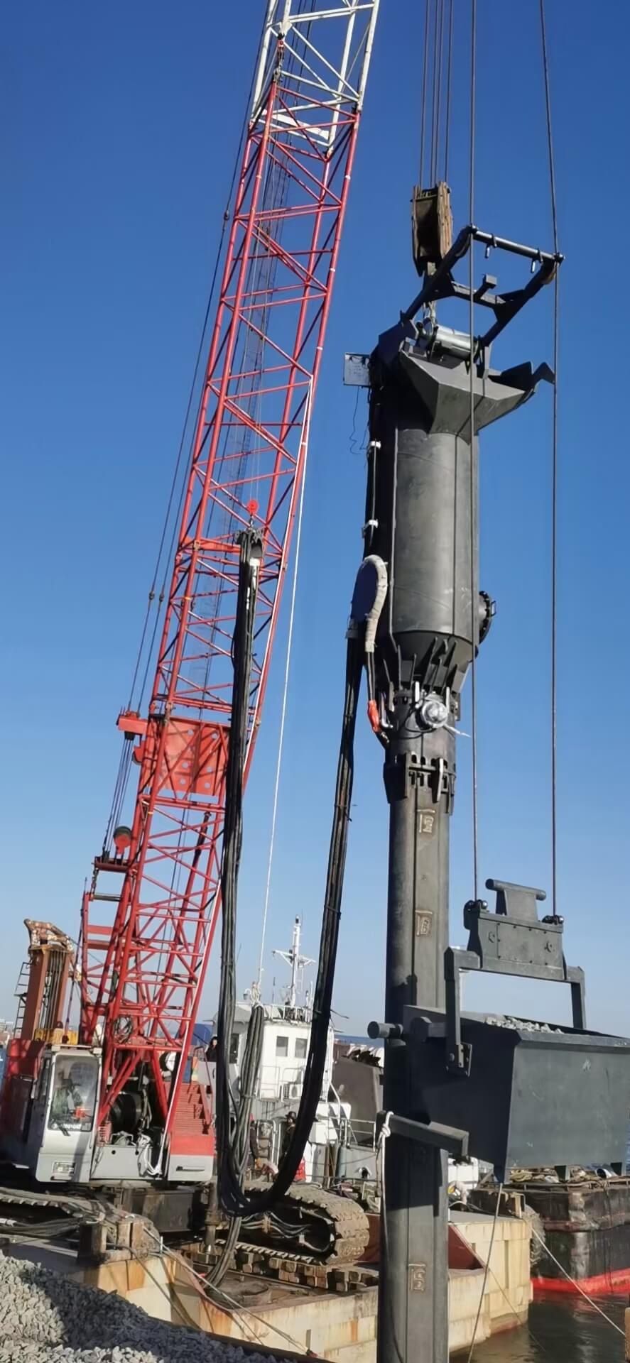
In geotechnical engineering, load transfer in weak soils depends heavily on the cross-sectional area of the reinforcing elements. Accurately determining the stone column diameter forms the baseline for mitigating settlement and preventing foundation failure. Oversizing these columns leads to excessive aggregate consumption and demands unnecessarily heavy machinery, driving up project overhead. Undersizing exposes the structure to severe risks, including bulging failures, differential settlement, and compromised structural integrity. Optimized stone columns present an economical and technically viable alternative to traditional deep piling. This holds true only when the diameter is precisely engineered to match the site's specific load requirements and soil stratigraphy. Achieving this requires aligning geotechnical design parameters—specifically diameter, length, and grid spacing—with the correct installation methodology and specialized machinery. When engineers match the right equipment to the designed column specifications, they ensure verifiable, long-term performance across the entire foundation footprint.
Diameter Dictates Capacity: The ultimate bearing capacity and settlement reduction of a stone column are mathematically bound by its cross-sectional area and the confining stress of the surrounding soil.
The 900–1200mm Standard: The 900 1200mm stone column range represents the industry sweet spot for balancing load-bearing requirements with installation efficiency in commercial, industrial, and urban projects.
Equipment Dependency: Achieving a consistent, design-specified diameter requires precise matching of vibro replacement equipment (probe size, amplitude, and eccentric force) to the specific soil profile.
Installation Method Matters: Bottom feed stone column techniques provide superior diameter control and quality assurance in highly stratified, expansive, or collapsible soils compared to top-feed methods.
The Engineering Physics of Stone Column Diameter
The primary objectives of installing stone columns are to increase the global shear strength of the soil matrix, accelerate radial consolidation, and mitigate liquefaction potential in seismically active zones. To achieve these outcomes, we must understand the underlying physics governing how a compacted aggregate column interacts with the native earth under structural loading.
Load-Bearing Capacity vs. Settlement Reduction
The relationship between column diameter and load capacity is highly non-linear. As the diameter increases, the area replacement ratio increases proportionally. The area replacement ratio is the ratio of the column's cross-sectional area to the total tributary area of the soil it reinforces. A higher area replacement ratio directly reduces the vertical stress applied to the native weak soil. The structural load concentrates on the stiffer aggregate matrix, which possesses a much higher internal friction angle than the surrounding clay or silt.
When you increase the diameter, you exponentially increase the volume of highly compacted stone resisting the downward force. This redistribution of stress limits vertical compression in the native soil, significantly reducing total and differential settlement. You cannot design an arbitrarily large diameter without considering the native soil's mechanical properties. The soil must be able to hold the stone in place.
Area Replacement Ratio by Grid Spacing and Diameter
Column Diameter (mm)
Grid Spacing (m) - Triangular
Tributary Area (m²)
Area Replacement Ratio (%)
800
1.5
1.95
25.8
900
1.8
2.81
22.6
1000
2.0
3.46
22.7
1200
2.5
5.41
20.9
The Role of Lateral Confinement
A fundamental geotechnical limitation dictates that a column can only expand to a diameter where the active outward pressure of the compacted stone equals the passive resistance of the surrounding soil. The native soil must possess sufficient undrained shear strength to provide this confining stress during loading.
If the designed diameter is too small relative to the applied vertical load, or if the surrounding soil lacks adequate confinement, the column experiences bulging failure. The vertical load forces the aggregate to yield laterally, pushing into the soft soil and causing the column to lose its structural integrity. Maximum bulging typically occurs at a depth of two to three times the column diameter below the working platform. Designing the correct diameter ensures the internal stresses remain below the threshold that triggers this lateral yielding.
Holistic Design Variables
You cannot design the diameter in a vacuum. Geotechnical engineers calculate it simultaneously with several other critical variables to ensure the system functions as a cohesive unit.
Column Length: Columns must extend through the compressible strata and terminate in a competent bearing layer to prevent punching failure at the toe.
Grid Spacing: The center-to-center distance between columns determines the tributary area. A wider spacing requires a larger diameter to maintain the target area replacement ratio.
Aggregate Quality: The angularity, hardness, and gradation of the backfill stone dictate the internal friction angle. Crushed stone with high angularity locks together under vibration, transferring loads outward into the soil more effectively than rounded river rock.
Stress Concentration Factor: This measures how much stiffer the column is compared to the soil. A larger diameter generally improves this factor, drawing more load away from the compressible clays.
Standard Sizing: Evaluating the 900 to 1200mm Stone Column Range
In heavy civil engineering, specific diameter ranges have become standardized based on decades of empirical data and equipment evolution. The 900 1200mm stone column range serves as the benchmark for most ground improvement applications. This range offers a reliable balance between structural performance and installation feasibility.
When to Specify 900mm Columns
Engineers typically specify 900mm columns for projects with moderate load-bearing requirements. Common field applications include low-rise commercial structures, highway embankments, and warehouse floor slabs resting on moderately compressible soils. In these scenarios, the structural loads are distributed over a wide area, and massive individual column capacities are not required.
The primary advantage of the 900mm specification is cost-efficiency. Smaller diameters require lower aggregate volumes, reducing material costs and the logistical overhead associated with hauling thousands of tons of stone to the site. You can install 900mm columns using standard-tier vibroflotation rigs. This makes them highly suitable for space-constrained urban environments where massive, high-energy rigs cannot operate due to access limitations or proximity to existing sensitive structures. A properly spaced grid of 900mm columns delivers significant settlement reduction without over-engineering the foundation.
When to Specify 1200mm Columns
Scenarios demanding maximum area replacement necessitate the specification of 1200mm columns. These applications include heavy industrial slabs, liquid storage tanks, bridge abutments, and sites located in high seismic risk zones prone to liquefaction. Highly expansive soils also benefit from larger diameters, as the increased mass of the stone provides better resistance against soil heave.
Achieving a 1200mm diameter requires higher-energy equipment. The vibrator must generate sufficient centrifugal force to displace the surrounding soil laterally and adequately compact the larger cross-sectional area of the aggregate. Using undersized equipment for a 1200mm design results in a loosely compacted core, negating the structural benefits of the larger diameter and leading to post-construction settlement.
Site Evaluation Steps for Sizing
Analyze the Cone Penetration Test (CPT) data to determine the undrained shear strength of the weakest soil layer.
Calculate the required area replacement ratio based on the structural engineer's maximum allowable settlement criteria.
Select a trial diameter (e.g., 1000mm) and calculate the required grid spacing.
Verify that the selected diameter does not exceed the lateral displacement capacity of the available vibroflotation equipment.
Adjust the diameter and spacing iteratively until you find the most cost-effective balance of aggregate volume and rig time.
How Installation Methods Influence Final Column Diameter
Designing a specific diameter on paper is only half the engineering challenge. Achieving that exact diameter in the field depends entirely on the construction technique. Different installation methods directly impact the as-built diameter, the integrity of the aggregate matrix, and the overall reliability of the ground improvement program.
Comparison of Installation Methods and Diameter Control
Installation Method
Delivery Mechanism
Diameter Consistency
Best Suited Soil Conditions
Risk of Soil Inclusion
Bottom Feed
Tremie pipe attached to the vibrator
High (Maintained from toe to surface)
High groundwater, highly cohesive, expansive, or collapsible soils
Very Low
Top Feed
Surface dumping into the open annulus
Variable (Prone to necking or collapse)
Stable, partially cohesive soils with low groundwater tables
High
Bottom Feed Stone Column Techniques
The bottom feed stone column method represents the industry standard for ensuring precise diameter control. This technique utilizes a specialized vibrator equipped with an integrated tremie pipe. The aggregate is loaded into a hopper at the surface, pressurized with air, and fed directly down the pipe to the tip of the vibrator.
This continuous delivery mechanism ensures that the stone is placed exactly where the compaction energy is highest. Because the vibrator remains in the ground while the stone is introduced, the hole is never left open or unsupported. This prevents hole collapse, a critical factor when working in high-groundwater environments, expansive clays, or highly cohesive soils. The bottom-feed method guarantees that the intended diameter is maintained consistently from the toe of the column all the way to the working surface. The operator lifts the probe in 0.5-meter increments, allowing the stone to fill the void, and then repenetrates the stone to force it laterally into the soil walls.
Top Feed Methods and Diameter Variability
Top-feed methods involve penetrating the soil with the vibrator, withdrawing it partially or completely to create an open hole, and then dumping aggregate from the surface using a loader. The vibrator is then re-inserted to compact the stone in lifts.
While historically common, top-feed methods present significant limitations in maintaining a consistent diameter. The primary risk is hole collapse. If the native soil yields before the stone reaches the bottom, the column experiences necking. Necking is a localized reduction in diameter that severely compromises load-bearing capacity. As the stone falls from the surface, it scrapes the sides of the borehole, dragging native clay or silt into the aggregate matrix. This soil inclusion reduces the internal friction angle of the column, diminishing its effectiveness and increasing the likelihood of bulging under load.
Selecting Vibro Replacement Equipment for Target Diameters
Procuring or renting the right machinery is the most critical operational decision in any ground improvement project. The capabilities of the vibro replacement equipment directly dictate the maximum achievable diameter and the density of the compacted stone.
Matching Probe Size and Amplitude
The physics of vibroflotation rely on the vibrator's amplitude and centrifugal force. As the eccentric weight spins inside the probe, it generates horizontal vibrations that displace the surrounding soil and compact the aggregate. The magnitude of this centrifugal force determines how far the soil can be pushed laterally.
To achieve a 1200mm diameter, the equipment must possess a high amplitude and substantial centrifugal force. If you use an undersized probe designed for 800mm columns to construct a 1200mm column, the vibration energy dissipates before reaching the outer edges of the aggregate. This results in a dense core surrounded by a loose, uncompacted outer ring. Under structural loading, this loose zone compresses, leading to excessive settlement and potential failure. You must match the eccentric force to the target diameter and the stiffness of the native soil.
Evaluating Stone Column Construction Equipment
When reviewing specifications for stone column construction equipment, engineers and contractors must evaluate several critical parameters to ensure field success.
Power Output (kW): Higher power ratings, typically between 130kW and 180kW, are mandatory for large diameters and deep penetrations in stiff soils. Lower kW rigs will stall or overheat when attempting to compact large volumes of stone.
Penetration Depth Capacity: The rig and extension tubes must be capable of reaching the designated bearing stratum without losing verticality. Deep deposits of soft clay may require rigs capable of 20-meter penetrations.
Real-Time Data Monitoring: Modern rigs feature onboard computers that continuously record ampere consumption, penetration depth, and stone volume per linear meter. This data is essential for verifying compaction effort and proving the as-built diameter to the client.
Vibrator Frequency: The frequency must match the resonant frequency of the soil and the aggregate to maximize compaction efficiency. Most modern rigs operate between 30 and 50 Hz.
Partnering with a Vibroflotation Equipment Supplier
Sourcing machinery goes beyond reading a specification sheet. Partnering with a reputable vibroflotation equipment supplier ensures that the equipment matches the specific demands of the soil profile. Contractors should vet suppliers based on their technical support capabilities, the reliability of their machinery under continuous heavy-duty cycles, and the immediate availability of spare parts.
A supplier with extensive field experience can provide invaluable guidance on matching eccentric force and probe dimensions to the target column diameter. They help you avoid the costly mistake of mobilizing an underpowered rig to a site with dense sand layers or highly cohesive clays. Proper equipment selection ensures field execution aligns perfectly with the geotechnical design.
Implementation Risks and Mitigation in Deep Foundation Ground Improvement
Executing deep foundation ground improvement requires rigorous field management. Theoretical designs must withstand the realities of subsurface variability and equipment operation. Field crews must be prepared to adjust parameters on the fly based on rig feedback.
Soil Confinement Loss and Over-Consumption
One of the most significant financial and structural risks occurs when installing columns in extremely soft soils, such as peat or very soft marine clays. Because these soils offer minimal passive resistance, the vibrator can push an uncontrolled amount of stone laterally.
This lack of confinement leads to massive, irregular diameters, resulting in severe aggregate over-consumption and immediate budget overruns. To mitigate this risk, operators utilize real-time rig data to monitor stone consumption per linear meter. Geotechnical engineers establish strict refusal criteria before mobilization. They define the maximum allowable amperage or stone volume per lift to prevent the contractor from endlessly pumping stone into a yielding soil matrix. If a specific depth interval consumes more than 150% of the theoretical volume, the operator must stop feeding stone, compact the existing material, and move up to the next lift.
Quality Control: Verifying As-Built Diameter
Because stone columns are installed blindly beneath the surface, robust quality control is mandatory to verify the as-built diameter and structural integrity.
Installation Parameters: Continuous recording of depth, stone consumption, and vibrator amperage provides the first line of verification. A consistent stone volume per depth interval confirms a uniform diameter. An amperage spike indicates the stone is fully compacted against the soil walls.
Plate Load Tests: Conducting static load tests on single columns or column groups verifies the actual bearing capacity and settlement characteristics of the improved ground. A steel plate is placed over the column head, and hydraulic jacks apply a load up to 150% of the design load while dial gauges measure settlement.
Cone Penetration Testing (CPT): Performing CPTs at the centroid between columns measures the increase in lateral stress and the densification of the native soil. This confirms the area replacement ratio is functioning as designed and the soil matrix has improved.
Aggregate Selection and Compaction Realities
The physical properties of the backfill stone interact directly with the chosen diameter and equipment. The aggregate must be hard, angular, and properly graded, typically between 20mm and 75mm. Angular stone locks together under vibration, creating a high internal friction angle that often exceeds 40 degrees.
If rounded river rock or improperly graded material containing too many fines is used, the stone will not interlock effectively, regardless of the vibrator's energy. This reduces the column's ability to transfer loads laterally, increasing the risk of bulging failure even if the correct diameter was achieved. The rig operator will notice that the amperage does not spike during repenetration, indicating the stone is displacing rather than compacting.
Conclusion
Finalize comprehensive soil investigation reports to determine the undrained shear strength and compressibility of the target strata before selecting a diameter.
Calculate the required area replacement ratio to establish the baseline diameter and grid spacing for your specific structural loads.
Consult with a specialized equipment supplier to match rig specifications, specifically centrifugal force and probe size, to the engineered diameter.
Establish strict real-time monitoring protocols and volume refusal criteria before mobilization to control aggregate consumption.
Mandate bottom-feed installation methods when working in high-groundwater or highly cohesive soils to prevent hole collapse and ensure diameter consistency.
FAQ
Q: How does stone column diameter affect bearing capacity?
A: Larger diameters increase the area replacement ratio, which distributes structural loads over a wider area of highly compacted, high-friction aggregate. This redistribution reduces the vertical stress on the native weak soil, thereby increasing the overall bearing capacity of the foundation system and significantly reducing total and differential settlement.
Q: What is the standard diameter for a stone column?
A: While specific diameters vary based on precise soil conditions and structural loads, the 900 to 1200mm range serves as the industry standard. This sizing provides an optimal balance of load-bearing performance, aggregate efficiency, and installation feasibility for most commercial, urban, and heavy civil applications.
Q: Why is a bottom feed stone column preferred for large diameters?
A: Bottom-feed systems utilize a tremie pipe to deliver stone directly to the vibrator tip while the probe remains in the ground. This continuous support prevents hole collapse and soil inclusion, ensuring a consistent, verifiable diameter from toe to surface, especially in weak, expansive, or water-bearing soils.
Q: How do you verify the as-built diameter of a stone column?
A: Verification relies on continuous real-time monitoring of stone consumption volume and vibrator amperage per depth interval during installation. This data is combined with post-installation physical verification methods, including Plate Load Tests on the column heads and Cone Penetration Testing (CPT) between the columns.
Q: Can any vibro replacement equipment install a 1200mm stone column?
A: No. Achieving a fully compacted 1200mm diameter requires high-energy construction equipment. The vibrator must generate sufficient amplitude and centrifugal force to displace the native soil laterally and fully compact the large cross-sectional area of the aggregate, preventing loose, uncompacted zones.
Q: What happens if the stone column diameter is too small?
A: If the diameter is too small relative to the applied vertical load, the column risks bulging failure. The structural load forces the aggregate to yield laterally into the surrounding soft soil due to insufficient cross-sectional area and inadequate passive soil confinement, leading to severe settlement.
Q: How does soil type limit the maximum stone column diameter?
A: The maximum achievable diameter is dictated by the passive resistance, or undrained shear strength, of the native soil. Extremely stiff soils resist lateral displacement, limiting the diameter. Conversely, extremely soft soils offer little resistance, which can lead to uncontrolled expansion and excessive stone consumption.